
Power converter system and method
a power converter and converter technology, applied in the direction of power conversion systems, ac-ac conversion, circuit arrangements, etc., can solve the problems of reducing the system efficiency, overheating the generator, and using very large and costly filters
Patent Information
- Authority / Receiving Office
- US · United States
- Patent Type
- Applications(United States)
- Current Assignee / Owner
- Publication Date
- 2007-05-31
Smart Images
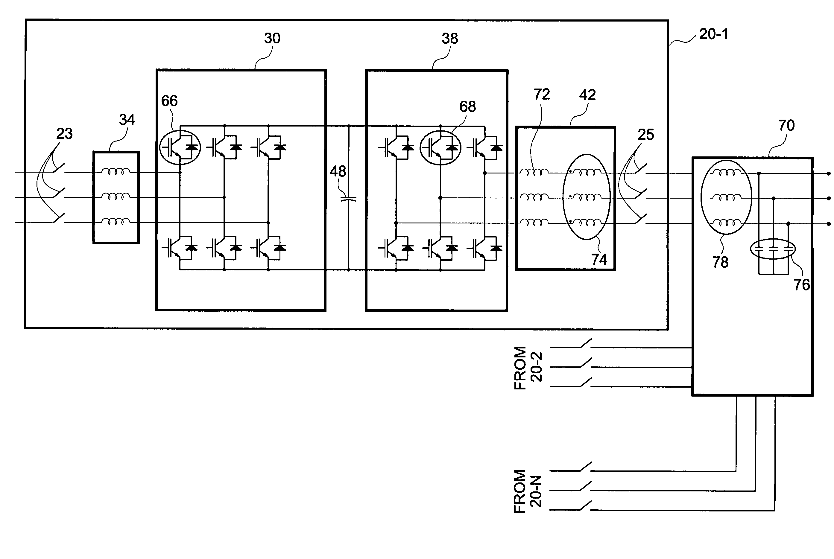
Figure 1 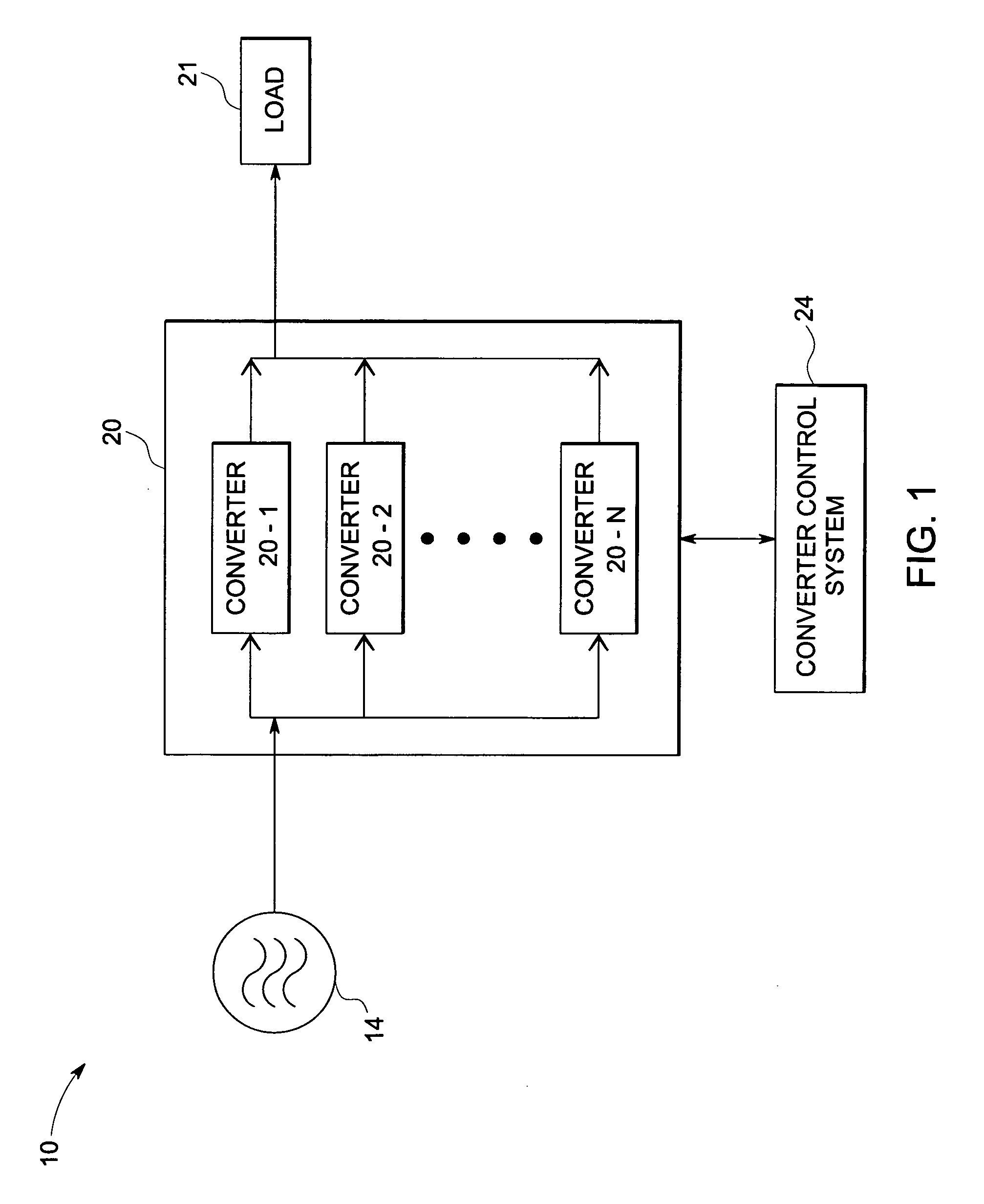
Figure 2 
Figure 3
Abstract
Description
BACKGROUND
[0001] The invention relates generally to power converter systems and more specifically to a method and system for operating a power converter system in an interleaved manner.
[0002] Many devices, such as wind turbines, include power converter systems. A power converter system is typically used to convert an input voltage, which may be fixed frequency alternating current, variable frequency alternating current, or direct current, to a desired output frequency and voltage level. A converter system usually includes several power semiconductor switches such as insulated gate bipolar transistors (IGBTs), integrated gate commutated thyristors (IGCTs or GCTs), or MOSFETs that are switched at certain frequencies to generate the desired converter output voltage and frequency. The converter output voltage is then provided to various loads. Loads as used herein are intended to broadly include motors, power grids, and resistive loads, for example.
[0003] Typically, power converter s...
Examples
Embodiment Construction
[0019]FIG. 1 is a block diagram of one embodiment of a power system 10 implemented according to one aspect of the invention. Power system 10 is configured for supplying power to a load 21. Each block is described in further detail below.
[0020] A generator source 14 is configured to generate an AC input power. The AC input power is provided to power converter system 20. The power converter system 20 comprises converter 20-1 through 20-N. The converters are coupled in parallel and configured to receive the AC input power from the generator source 14. The power converter system 20 is configured to convert the AC input power to an output power. The output power is provided to load 21. In one embodiment, the output power has a fixed frequency. Loads may include motors, power grids, and resistive loads, for example. Although grids are traditionally suppliers of power, in some wind turbine system embodiments, wind turbine power is supplied to a utility grid which acts as a load in such em...