
Common mode filter system and method for a solar power inverter
Patent Information
- Authority / Receiving Office
- US · United States
- Current Assignee / Owner
- Publication Date
- 2008-11-27
Smart Images
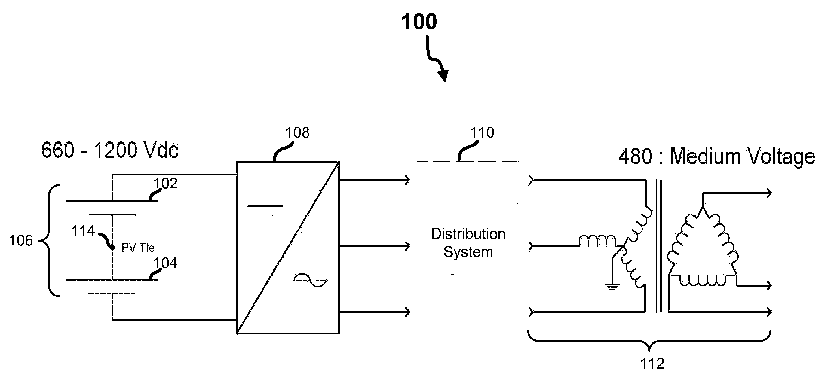
Figure 1 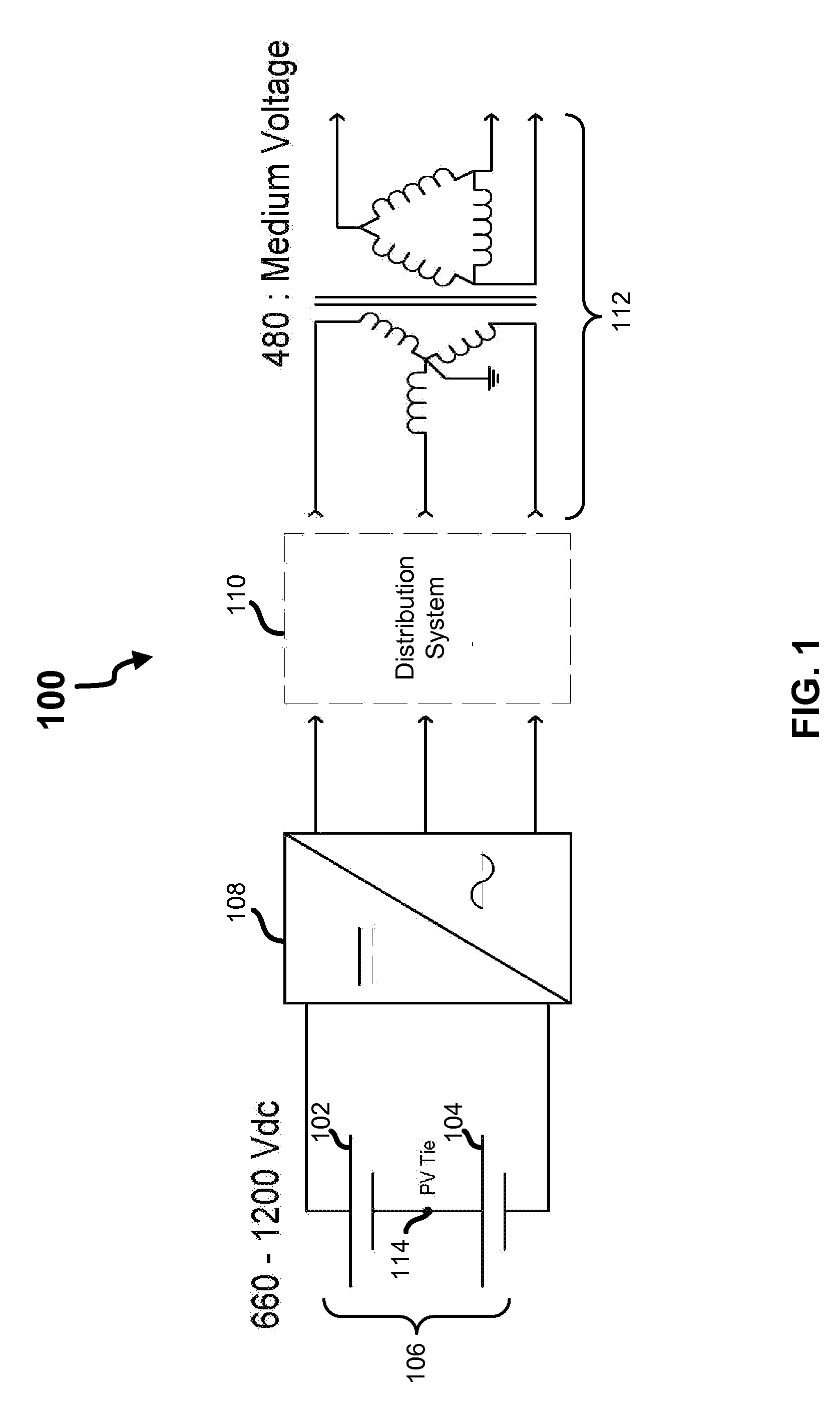
Figure 2 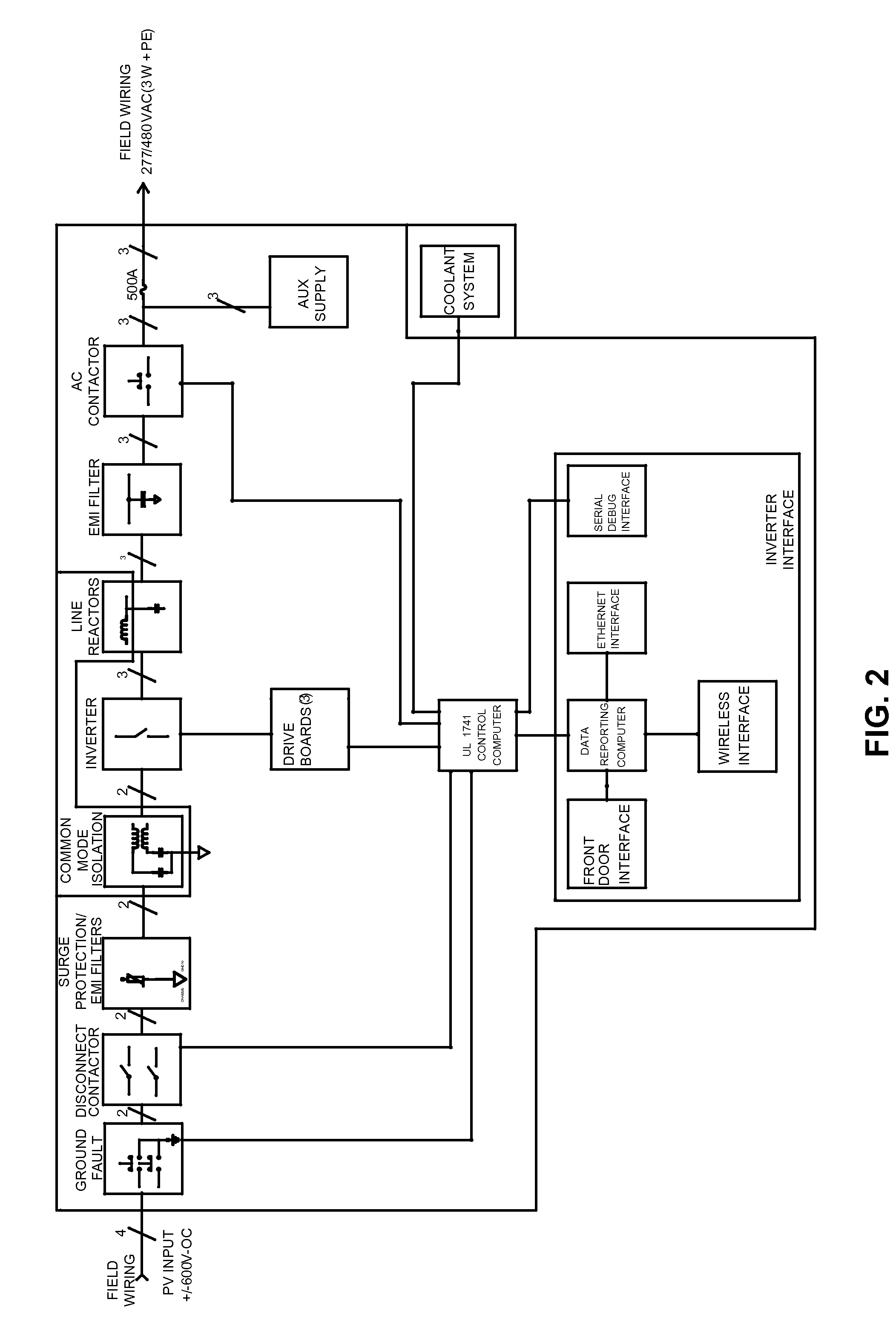
Figure 3
Abstract
Description
PRIORITY
[0001] The present application claims priority to provisional patent application No. 60 / 939,807, filed May 23, 2007, entitled: COMMON MODE FILTER FOR SOLAR INVERTER, which is incorporated by reference herein in its entirety.FIELD OF THE INVENTION
[0002] This invention relates generally to apparatus and methods for converting solar energy to electrical energy, and more specifically to apparatus and methods for more efficient conversion of solar energy to electrical energy.BACKGROUND OF THE INVENTION
[0003] In photovoltaic (PV) energy systems, inverters are used to convert DC electrical energy that is generated by photovoltaic panels to AC electrical energy that is compatible with the AC distribution systems that are built into the infrastructure of residential, commercial, industrial premises, and large ground mounted solar farms.
[0004] Typically an inverter is hard grounded (e.g., on the negative rail of the inverter DC input) and an isolation transformer is utilized in connection...
Examples
Embodiment Construction
[0019]Referring first to FIG. 1, shown is a block diagram an exemplary embodiment of the present invention. As shown, in this embodiment a first set 102 and a second set 104 of photovoltaic panels are arranged to create a bipolar panel array 106 that is coupled to an inverter 108, which is disposed between the panel array 106 and a distribution system 110. As shown, the distribution system 110 in this embodiment is coupled to the secondary side of a wye-configured medium-voltage to 480 / 277 three-phase transformer 112 that is grounded at its star point.
[0020]The illustrated arrangement of the components depicted in FIG. 1 is logical and not meant to be an actual hardware diagram; thus, additional components can be added or combined with the components that are depicted in an actual implementation. It should also be recognized that the components, in light of the disclosure herein, may be readily implemented by one of ordinary skill in the art.
[0021]As an example, the inverter 108 is ...