
Method and apparatus for aligning microbeads in order to interrogate the same
a technology of microbeads and interrogation, which is applied in the field of methods and apparatus for processing information contained on microbeads, can solve the problems of insufficient different codes, inability to withstand harsh temperature, chemical, nuclear and/or electromagnetic environments, and insufficient existing technologies such as bar codes, to achieve reliable and repeatable transportation of all beads, and low cost. , the effect of fast and effective/reliable movemen
Patent Information
- Authority / Receiving Office
- US · United States
- Patent Type
- Applications(United States)
- Current Assignee / Owner
- Publication Date
- 2010-10-07
- Estimated Expiration
- Not applicable · inactive patent
Smart Images
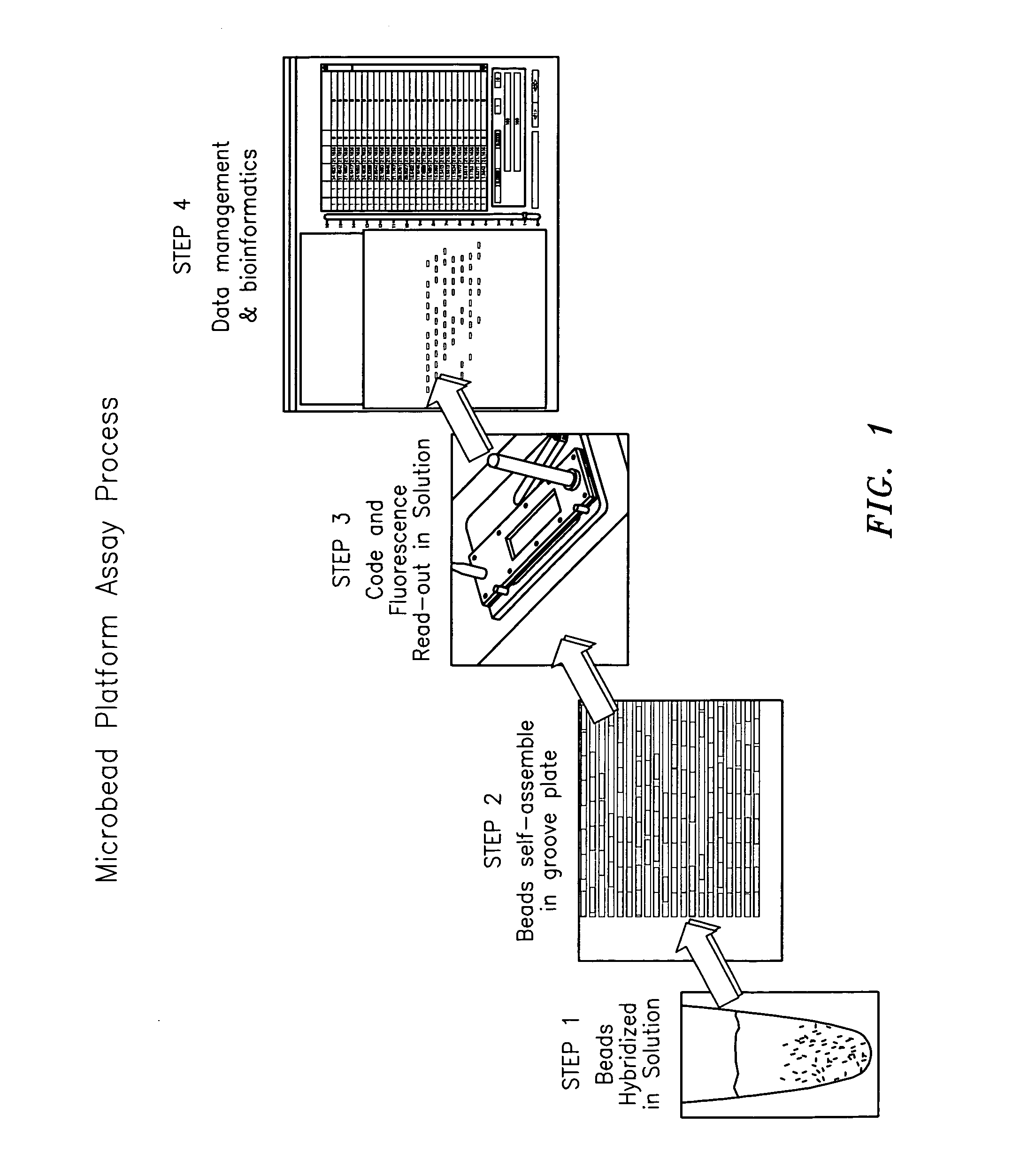
Figure 1 
Figure 2 
Figure 3
Abstract
Description
CROSS REFERENCES TO RELATED APPLICATIONS
[0001] The present application claims the benefit of: U.S. Provisional Application Ser. No. 60 / 609,583, filed Sep. 13, 2004, entitled “Improved Method and Apparatus for Aligning Microbeads in Order to Interrogate Same” (Docket No. CV-0082 PR); Ser. No. 60 / 610,910, filed Sep. 17, 2004, entitled “Method and Apparatus for Aligning Microbeads in Order to Interrogate Same” (Docket No. CV-0086 PR); and Ser. No. 60 / 610,833, filed Sep. 17, 2004, entitled “Method and Apparatus for Transporting and Kitting Microbeads” (Docket No. CV-0087 PR); and is a continuation-in-part of: U.S. patent application Ser. No. 10 / 661,836, filed Sep. 12, 2003, entitled “Method And Apparatus For Aligning Microbeads In Order To Interrogate The Same” (Docket No. CV-0042), and Ser. No. 11 / 063,665, filed Feb. 22, 2005, entitled “Multi-well Plate with Alignment Grooves for Encoded Microparticles” (Docket No. CV-0053 US), all the above of which are incorporated herein by referen...
Examples
Embodiment Construction
[0089]FIG. 1 shows, by way of example, steps of a microbead assay process which uses the microbead technology of the present invention. The steps of the assay process shown in FIG. 1 include a first step in which the microbeads are used in a solution; a second step in which the microbeads are aligned in a desired manner; a third step in which the code and florescence in and / or on the microbeads are read-out; and a fourth step in which the information related to the code and florescence is processed in relation to data management and bioinformatics. The present invention primarily relates to step 2 wherein the microbeads are uniquely aligned so the longitudinal axis of the microbeads is positioned in a fixed orientation relative to the code and florescence reading device, as well as relating to a lesser extent to step 3. It is important to note that the scope of the present invention is not intended to be limited to any particular type or kind of assay process or other process in whi...