
Optical sensing apparatus, filter apparatus, and projector with Anti-dust structure
a technology of optical sensing and filtering, applied in the direction of camera filters, instruments, transportation and packaging, etc., can solve the problems of decreasing achieve the effect of reducing the opportunity reducing the chance for the later dust to deposit, and reducing the air flow passing by the optical sensor
Patent Information
- Authority / Receiving Office
- US · United States
- Patent Type
- Applications(United States)
- Current Assignee / Owner
- Publication Date
- 2011-10-20
Smart Images
Figure 1 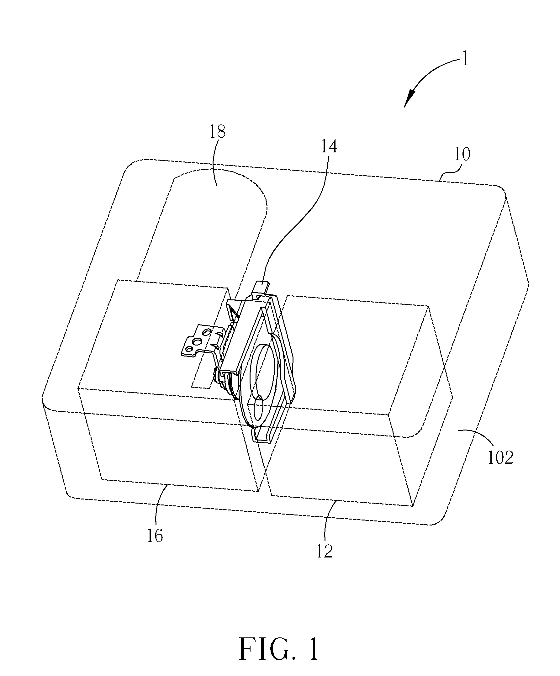
Figure 2 
Figure 3
Abstract
Description
BACKGROUND OF THE INVENTION
[0001] 1. Field of the Invention
[0002] The invention relates to an optical sensing apparatus, a filter apparatus, and a projector, and especially relates to an optical sensing apparatus, a filter apparatus, and a projector with anti-dust structure.
[0003] 2. Description of the Prior Art
[0004] As the dependence on electronic equipment of people increases, the adaptability to environment of the electronic equipment is promoted. In general, a housing of electronic equipment generating heat has a plurality of vents formed thereon for air to pass through for taking away heat generated in operation by electronic components inside the housing. However, in some environments, such as arid zones, there is often fine dust floating in the air. The fine dust enters the housing with an air flow, and a part of the dust deposits on the surfaces of the electronic components. This situation does not matter for a general requirement of heat dissipation. But for an electronic comp...
Examples
Embodiment Construction
[0022]Please refer to FIG. 1, which is a schematic diagram of an interior structure of a projector 1 according to a preferred embodiment of the present invention. The projector 1 includes a housing 10, a light source apparatus 12, a filter apparatus 14, an optical modification apparatus 16, and a projection lens 18. The housing 10 forms an accommodating space 102 therein for accommodating the light source apparatus 12, the filter apparatus 14, the optical modification apparatus 16, the projection lens 18, and other required electronic components. Light emitted from the light source apparatus 12 passes through the filter apparatus 14 to provide required color lights to the optical modification apparatus 16. The optical modification apparatus 16 can include a digital micro-mirror device (DMD) or a liquid crystal display (LCD) for modifying the color lights to form required images which are projected on a screen through the projection lens 18 later. In order to highlight the position o...