
Controlled discharge ostomy appliance and shield therefor
a technology of ostomy and shield, which is applied in the field of controlled discharge ostomy appliance and an auxiliary device therefor, can solve the problems of reducing the efficacy of the seal, and achieve the effects of reducing the damping characteristic of the seal, reducing the damping characteristic, and facilitating the change of the shape of the seal
Patent Information
- Authority / Receiving Office
- US · United States
- Patent Type
- Applications(United States)
- Current Assignee / Owner
- Publication Date
- 2012-07-12
Smart Images
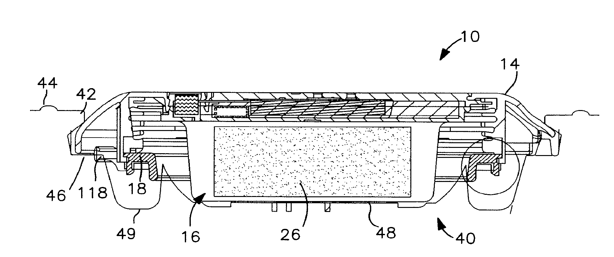
Figure 1 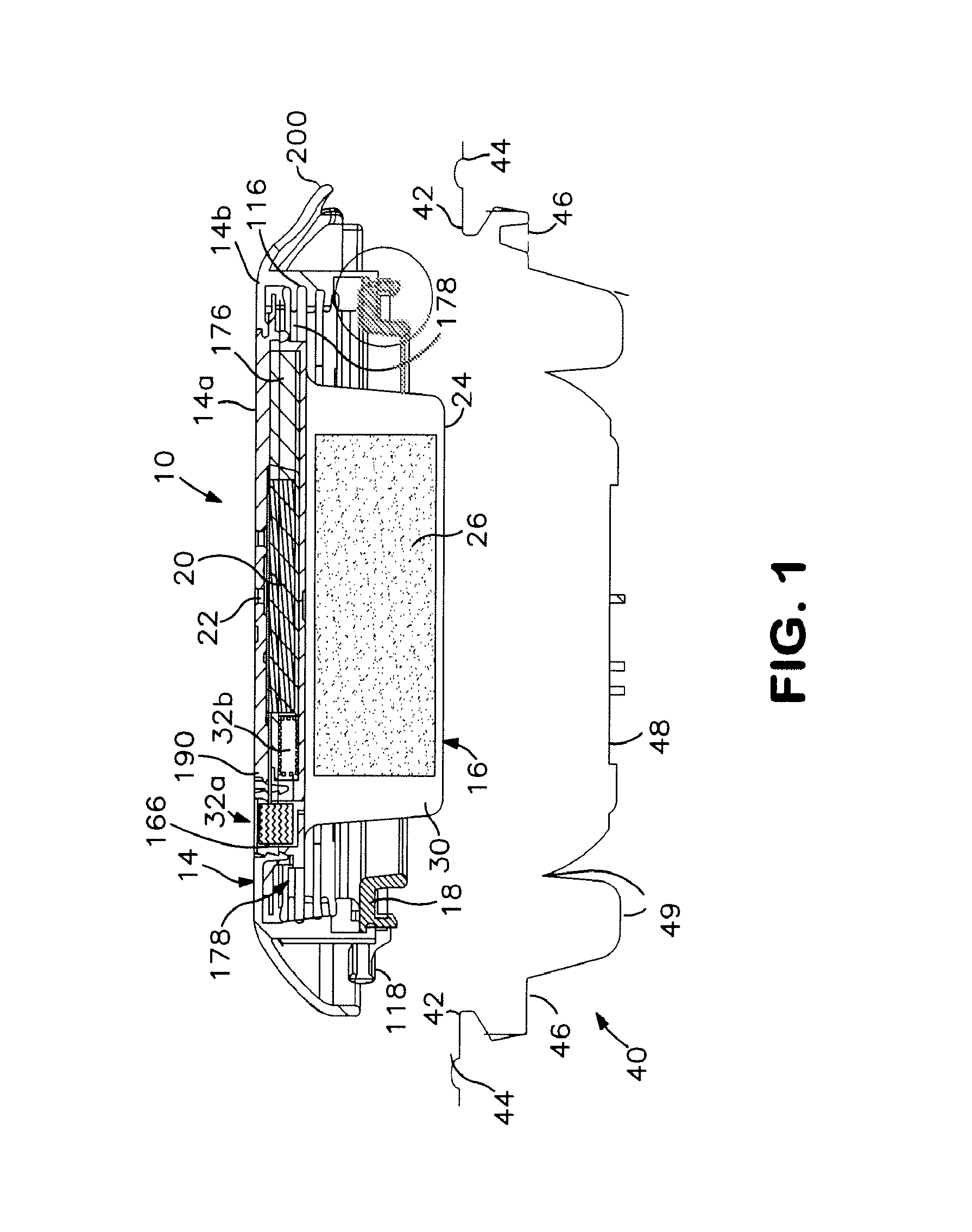
Figure 2 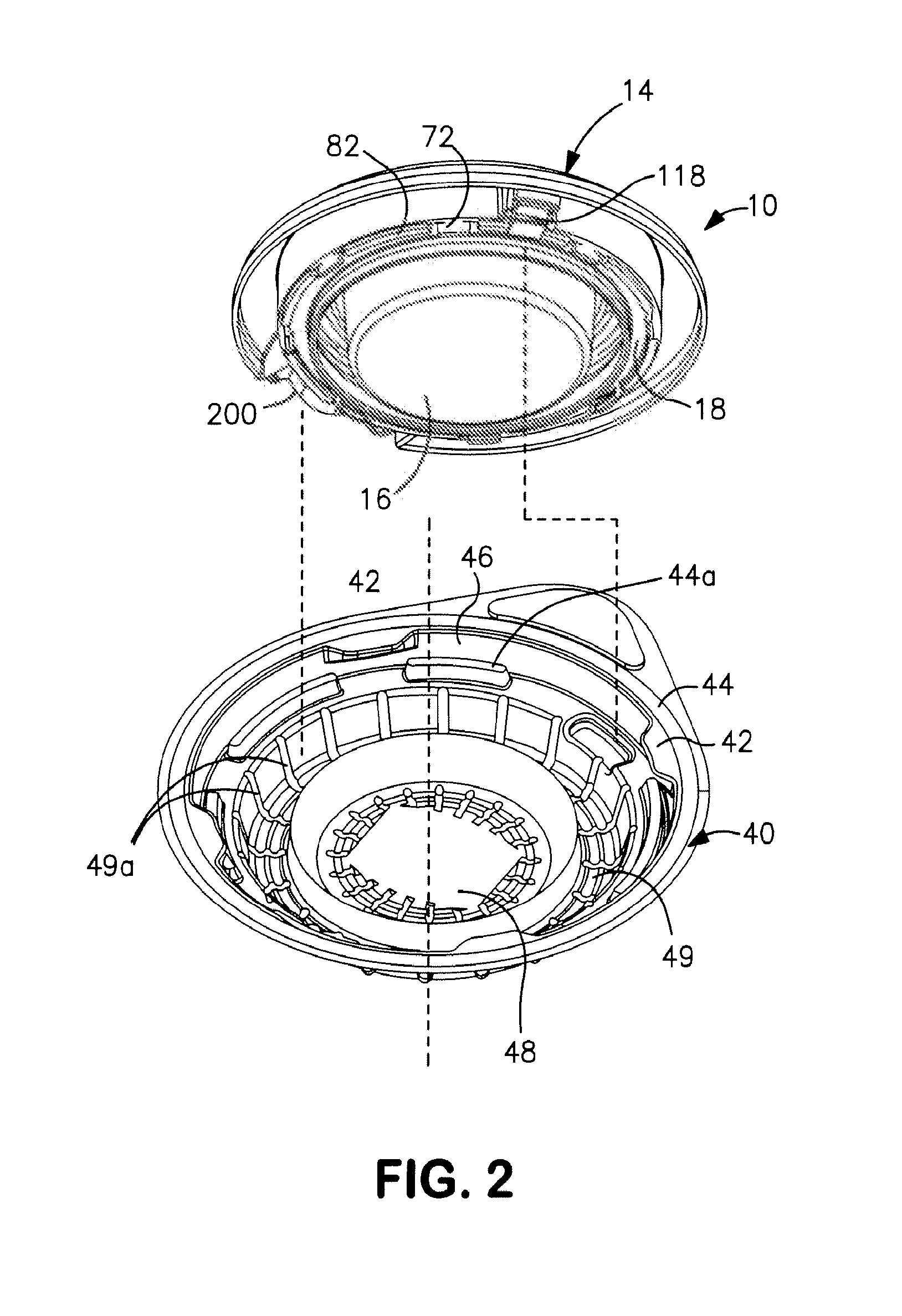
Figure 3
Abstract
Description
FIELD OF THE INVENTION
[0001] The present invention relates to a controlled discharge ostomy appliance and an auxiliary device therefor. The auxiliary device may, for example, be a shield or packaging for the controlled discharge ostomy appliance.BACKGROUND TO THE INVENTION
[0002] U.S. Pat. No. 6,723,079 and EP-A-1348412 describe controlled discharge ostomy devices including an inflatable membrane seal for creating a temporary conformal closure of the stoma. The inflatable seal comprises a sealed chamber having an inflation port closed by a check valve. After having fitted the appliance at a stoma, the seal is inflated by coupling an external inflation source, for example a pump or a syringe, to the check valve. Once the inflation fluid has been injected into the chamber, the check valve seals the chamber preventing loss of inflation fluid and preserving the inflation state.
[0003] Such a system can be comfortable to fit and provide good seal performance, but may require careful design. O...
Examples
first embodiment
[0095]A second aspect of the preferred embodiment relates to a coupling member arrangement for making a press-fit with a body-side coupling member for fitting the appliance at a stoma. This aspect may be used in combination with the first aspect, or independently of the first aspect. The following description focuses on a coupling for the appliance, but this embodiment may also use any combination of features from the first embodiment as if described in whole combination.
[0096]As best seen in FIGS. 9-11, the mounting device comprises a first member (first coupling member or appliance-side coupling member) 18 distinct from the cover 14 (second member). The first member 18 is of closed loop shape (e.g. annular in this embodiment). The first member 18 has a base 70 carrying a coupling formation for mechanically engaging the body-side coupling member 54 of the body fitment 50. The coupling formation comprises a plurality of lugs 72 depending from the base 70 at spaced apart positions ar...
second embodiment
[0115]The invention envisages various possible designs for releasing or relaxing the attachment to the body-side coupling member 54 when the user desires to remove the appliance 10 after it has been used. In one form (not shown), the cover 14 may be shiftable from the locked position back to the unlocked position, in order to remove the bracing effect on the lugs 72, and allow easier separation. However, in the second embodiment, the appliance 14 includes the following additional features:
(i) a single-use feature of the cover 14 for obstructing attachment of the device to the body fitment 50 more than once. The single-use feature optionally comprises at least one frangible portion 114 of the cover. The frangible portion 114 may extend into or through the bracing portion 80. The single use-feature 114 is optionally associated with a grippable tab 200
(ii) an expandable / collapsible waste collector 116 having an entrance opening sealed to the first member 18, to define an entry for stom...