
Voltage converter and voltage converter system including voltage converter
a voltage converter and power supply system technology, applied in the direction of motor/generator/converter stopper, dynamo-electric converter control, etc., can solve the problem of reducing the driving force of the vehicle, excessive voltage applied to the switching element in the boost circuit, and nonlinear (sudden) increase, etc. problem, to achieve the effect of suppressing the generation of magnetic noise from the direct-current power supply
Patent Information
- Authority / Receiving Office
- US · United States
- Current Assignee / Owner
- Publication Date
- 2012-09-13
Smart Images
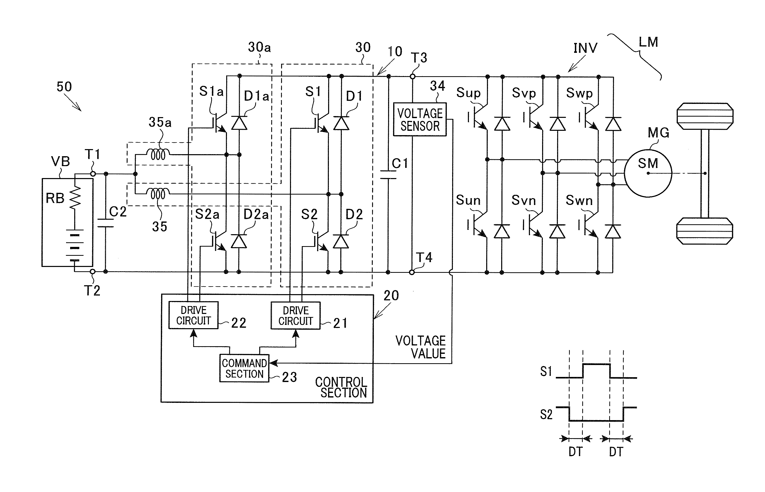
Figure 1 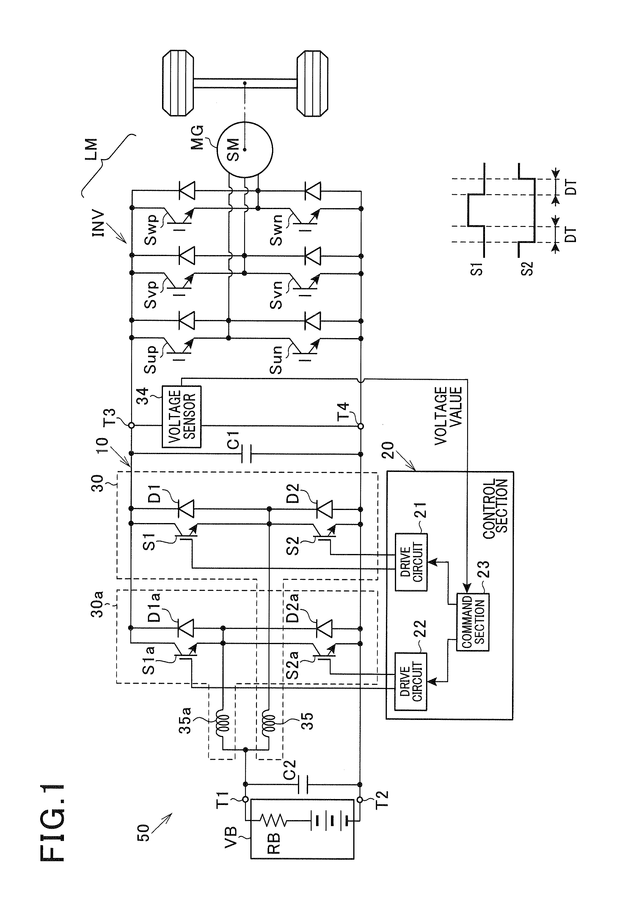
Figure 2 
Figure 3
Abstract
Description
CROSS REFERENCE TO RELATED APPLICATION
[0001] This application is based on and claims the benefit of priority from earlier Japanese Patent Application Nos. 2011-53959, 2011-53960 and 2011-286680 filed on Mar. 11, 2011, Mar. 11, 2011 and Dec. 27, 2011 respectively, the descriptions of which are incorporated herein by reference.BACKGROUND
[0002] 1. Technical Field
[0003] The present application relates to a voltage converter and a power supply system including the voltage converter. In particular, the present application relates to technology for converting the voltage of direct-current voltage supplied from a battery and using the converted voltage to drive an electric vehicle.
[0004] 2. Description of the Related Art
[0005] As a power supply device for electric vehicles, a power supply device is widely used that increases the voltage of a direct-current power supply, such as a battery, using a boost circuit and supplies a high voltage that is higher than the battery voltage to a drive section...
Examples
Embodiment Construction
[0035]An embodiment applied to a power supply device 50 that supplies power to a drive device of a vehicle of the present application will hereinafter be described with reference to the drawings.
[0036]FIG. 1 is a system configuration diagram of a configuration of the power supply device 50 according to the embodiment.
[0037]The power supply device 50 supplies direct current power, i.e., DC power, to a electrical load LM that is a drive device (a three-phase alternating-current (AC) motor system, described hereafter) of a vehicle. The power supply device 50 includes a direct-current (DC) battery VB, a voltage converter 10, and a control section 20. The voltage converter 10 provides a voltage boosting function and a voltage reducing (step-down) function. In the voltage boosting function, the voltage converter 10 increases the voltage of the direct-current power supplied from the DC battery VB and applies the electrical load LM with the boosted voltage (power). In the voltage step-down ...