
A multi-switch power factor correction method, system and electronic equipment
A technology of power factor correction and electronic equipment, applied in the field of correction, multi-switch power factor correction method, system and electronic equipment, can solve the problems that can not be used for reference and application of bridgeless single-phase APFC, etc., to facilitate model selection and heat dissipation treatment , novel design, reduced switching loss and conduction loss
Patent Information
- Authority / Receiving Office
- CN · China
- Patent Type
- Patents(China)
- Current Assignee / Owner
- Publication Date
- 2018-10-19
Smart Images
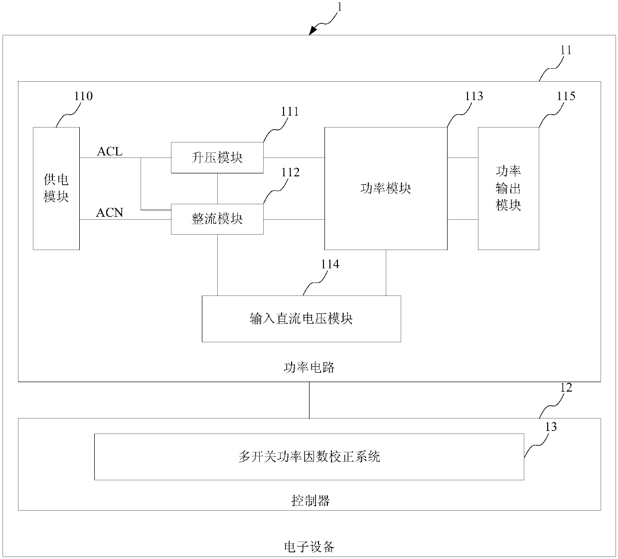
Figure 1 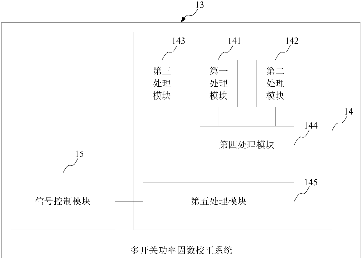
Figure 2 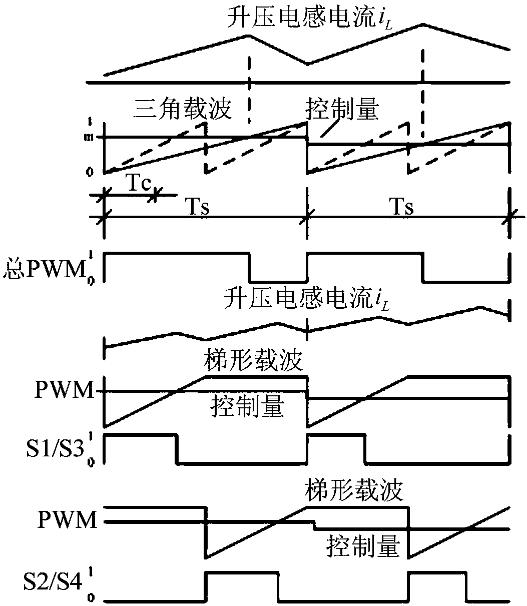
Figure 3
Abstract
Description
technical field
[0001] The invention belongs to the technical field of power electronic converters, and relates to a correction method and system, in particular to a multi-switch power factor correction method, system and electronic equipment. Background technique
[0002] The widely used single-phase power factor corrector (PFC) is a single-phase active power factor corrector (APFC), including bridge type and bridgeless type, which has been widely used in the front of the AC-DC converter of the frequency conversion home appliance power circuit stage circuit, that is, as an AC-DC converter. With the popularization and application of high-power inverter air conditioners, etc., the efficiency requirements for single-phase APFC are increasing day by day. Since the bridgeless single-phase APFC has the advantages of fewer power devices and low conduction loss at the same time, the potential efficiency is high, and it has attracted more and more attention. But so far, the tradit...
Examples
Embodiment 1
[0049] This embodiment provides an electronic device, and the electronic device includes:
[0050] The power circuit is used to provide an input DC voltage signal, an output DC voltage signal, and a boosted current signal; the power circuit includes a multi-stage parallel power module, a boost module connected to the multi-stage parallel power module, and a power The power output module connected to the module and the booster module;
[0051] A controller connected to the power circuit, the controller including a multi-switch power factor correction system.
[0052] The electronic device provided by this embodiment will be described in detail below with reference to the figures. see figure 1 and figure 2 , which are respectively shown as a schematic structural diagram of the electronic device in an embodiment and a circuit diagram of the electronic device in an embodiment. Such as figure 1 and figure 2 As shown, the electronic device 1 includes a power circuit 11 and a...
Embodiment 2
[0079] This embodiment provides a multi-switch power factor correction method, which is applied to a multi-stage parallel power module, a boost module connected to the multi-stage parallel power module, and a power module connected to the boost module. The power circuit of the power output module. see Figure 5 , is a schematic flowchart of a multi-switch power factor correction method in an embodiment. Such as Figure 5 As shown, the multi-switch power factor correction method includes the following steps:
[0080] S1, receiving an input DC voltage signal, an output DC voltage signal, and a boosted current signal from the power circuit;
[0081]S2. Logically process the input DC voltage signal, the output DC voltage signal, and the boosted current signal to form multiple pulse width modulation driving signals; the i-th pulse width modulation driving signal and the i+1th pulse width modulation The driving signals are phase-shifted by a preset angle, that is, 1 / N switching ...