
Computer system, migration method, and management server
Patent Information
- Authority / Receiving Office
- US · United States
- Current Assignee / Owner
- Publication Date
- 2013-09-12
- Estimated Expiration
- Not applicable · inactive patent
Smart Images
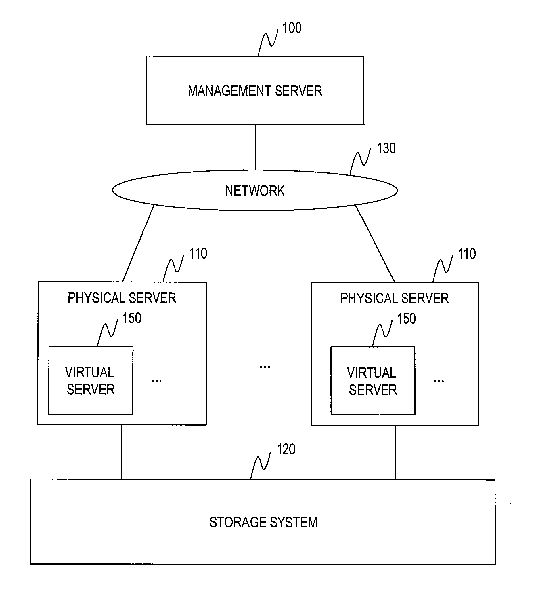
Figure 1 
Figure 2 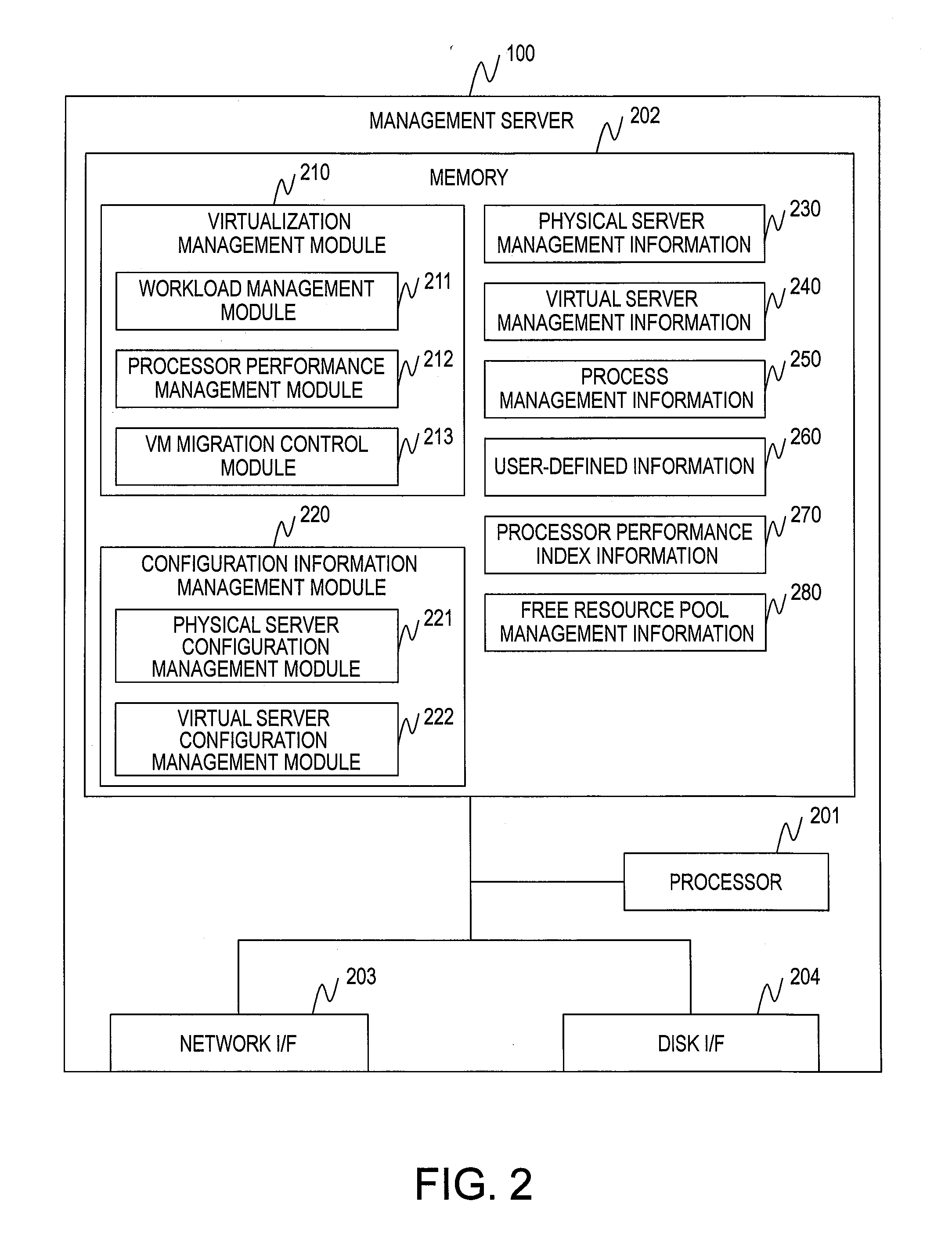
Figure 3
Abstract
Description
BACKGROUND OF THE INVENTION
[0001] This invention relates to a migration technology for migrating a virtual server operating on a physical server in a cloud environment.
[0002] In the cloud environment, servers having different performances are mixed. For example, a server has a CPU high in clock frequency and a server has a CPU low in clock frequency are mixed. In a resource pool, a total value (total value of clock frequencies in the case of CPUs) of resource amounts included in the respective server devices included in the resource pool is managed as a resource amount of the resource pool.
[0003] For example, a resource pool including four CPUs each being a clock frequency of 3 GHz, and a resource pool including six CPUs each being a clock frequency of 2 GHz both have a total value of the clock frequencies of 12 GHz, and are thus treated as resource pools having the same CPU resources.
[0004] A user uses a virtual server device (VM) constructed by using the server device, thereby providi...
Examples
first embodiment
[0045]In a first embodiment, a description is given of a virtualization technology by means of the VM method.
[0046]FIG. 1 is an explanatory diagram illustrating a configuration example of a computer system according to the first embodiment of this invention.
[0047]The computer system includes a management server 100, physical servers 110, and a storage system 120.
[0048]The management server 100 and the physical servers 110 are coupled to each other via a network 130. As the network 130, for example, a LAN, a WAN, or the like is conceivable.
[0049]Moreover, the physical servers 110 and the storage system 120 are coupled to each other directly or via a SAN or the like.
[0050]The management server 100 manages the entire computer system. A hardware configuration and a software configuration of the management server 100 are described later with reference to FIG. 2.
[0051]The physical server 110 is a computer on which virtual servers 150 operate so that a user provides a service. A hardware c...
second embodiment
[0352]In a second embodiment, a description is given of the LPAR method. It should be noted that differences from the first embodiment are mainly described.
[0353]Configurations of the computer system, the management server 100, the physical servers 110, and the storage system 120 according to the second embodiment are the same as those of the first embodiment, and a description thereof is therefore omitted.
[0354]The LPAR method is different in how to assign resources to the virtual servers 150.
[0355]FIG. 24 is an explanatory diagram illustrating a logical configuration of the computer system according to the second embodiment of this invention.
[0356]The virtualization module 310 logically divides the resources included in the physical server 110, and assigns an LPAR 2400 constituted by the logically divided resources to the virtual server 150.
[0357]In the example illustrated in FIG. 24, the LPAR 2400 includes a processor core 2410, a storage area 2420, and an LU 502. The resources a...