

Rotatable fixture
Patent Information
- Authority / Receiving Office
- US · United States
- Current Assignee / Owner
- Publication Date
- 2018-06-07
Smart Images
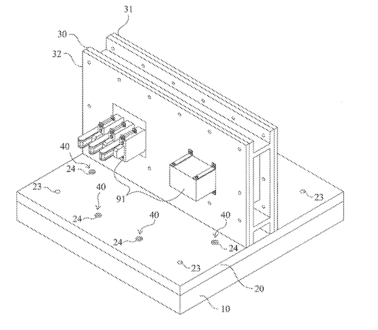
Figure 1 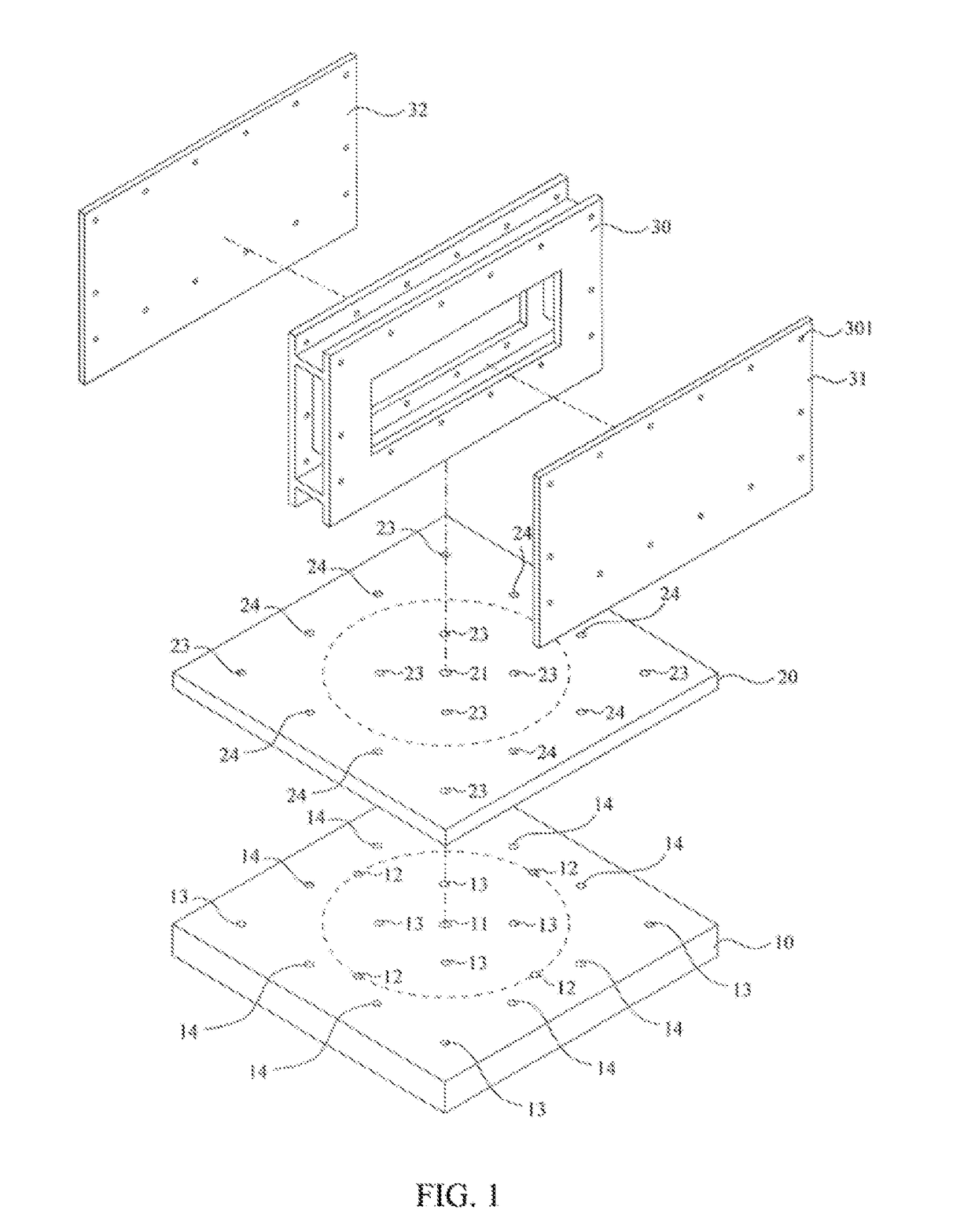
Figure 2 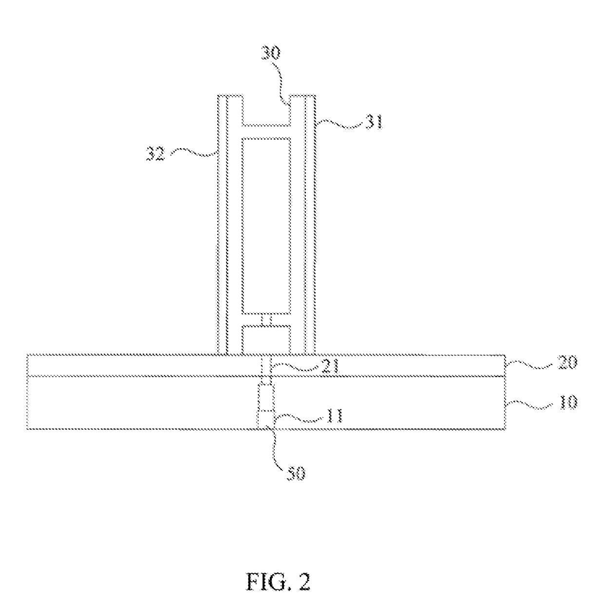
Figure 3
Abstract
Description
CROSS-REFERENCE TO RELATED PATENT APPLICATION
[0001] This application claims the benefit of Taiwan Patent Application No. 105140122, filed on Dec. 5, 2016, in the Taiwan Intellectual Property Office, the disclosure of which is incorporated herein in its entirety by reference.BACKGROUND OF THE INVENTIONField of the Invention
[0002] The present invention is related to a fixture for use in test of shake table to fasten a device, and more particularly to a self-rotating universal fixture for fastening a device under test.Description of the Prior Art
[0003] To ensure the safe operation of nuclear power plants, relevant equipments used in nuclear power plants are designed to sustain structural integrity and maintain its safety function during and after earthquake. In order to achieve this goal, quality of the equipment is granted through seismic qualification test, and a shake table is used for performing seismic qualification test. Generally speaking, during the seismic qualification test, the...
Examples
Embodiment Construction
[0018]Referring to FIG. 1, a perspective exploded view of a rotatable fixture according to a preferred embodiment of the present invention is shown. The rotatable fixture includes a base 10, a rotating disc 20, a fastening frame 30, and a pair of fixing plates 31, 32. The base 10 is shaped as a plate having a plurality of perforations thereon. The perforation 11 located in the center of the base 10 is set to allow a central axle 50 to be installed therein and past therethrough. Referring to FIG. 3A and FIG. 4A, the central axle 50 includes a central cone 51, a spring 52, and a headless screw bolt 53, all of which are sequentially mounted in the perforation 11 of the base 10. The front end of the central cone 51 is exposed through the perforation 11 of the base 10 for allowing the rotating disc 20 to be mounted thereon, and the flange located in the rear end of the central cone 51 contacted with the spring 52. The spring 52 provides the lift force to pop up the base 10 therethrough t...