
Light module for LCD panel
Patent Information
- Authority / Receiving Office
- US · United States
- Current Assignee / Owner
- Publication Date
- 2005-03-29
- Estimated Expiration
- Not applicable · inactive patent
Smart Images
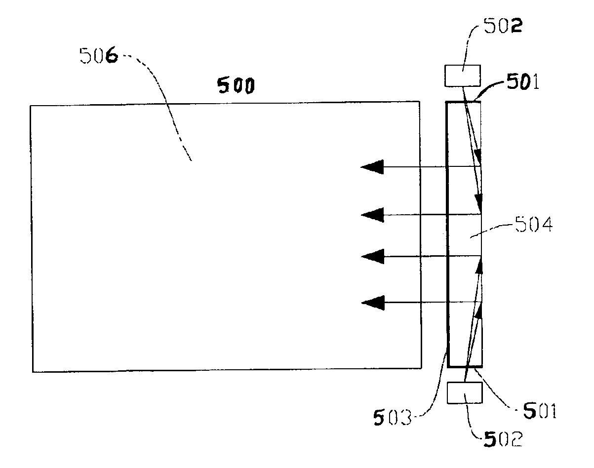
Figure 1 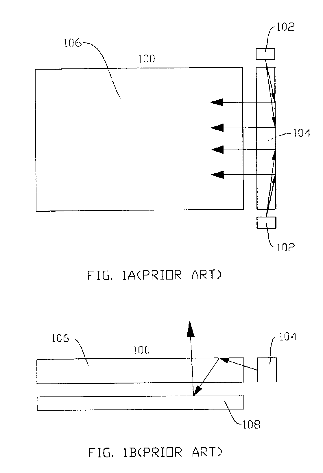
Figure 2 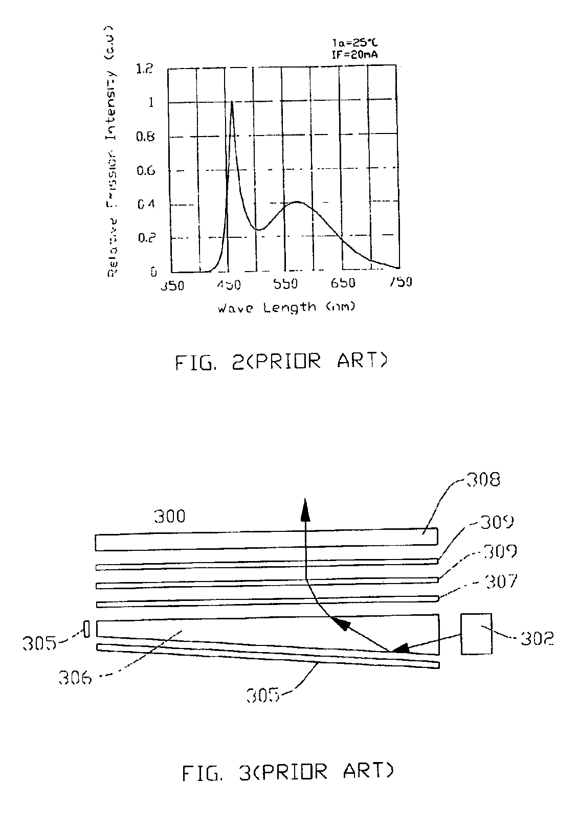
Figure 3
Abstract
Description
BACKGROUND OF THE INVENTION1. Field of the InventionThe present invention generally relates to an improved light module with LED light source for LCD panel. More specifically, the present invention relates to an improved light module with LED light source for LCD panel wherein Light-receiving surfaces of LGP (light guide plate), light-receiving surfaces of LGS (light guide stick) or light-emitting surfaces of LGS are coated with the mixed fluorescent powder and the white light with triple wavelength is made by the light rays emitted from UV LED to excite the mixed fluorescent powders.2. Description of the Prior ArtThe visions of the liquid crystal display (LCD) are extremely excellent since the displayed figures or pictures are not offensive to the eyes of human being unlike light emitting diode (LED). But it is one of the drawbacks of LCD that an additional light module is needed in order to show figures or pictures on the screen under the dark circumstance because LCD does not hav...
Examples
Embodiment Construction
Some sample embodiments of the present invention will now be described in greater detail. Nevertheless, it should be recognized that the present invention can be practiced in a wide range of other embodiments besides those explicitly described, and the scope of the present invention is expressly not limited except as specified in the accompanying claims.
Regarding the preferred embodiment of the present invention, please refer to the structure of the front light module of LCD panel 500 as illustrated in FIG. 5A and FIG. 5B. It includes the UV (ultraviolet) LED 502 is used as the light source, the light-receiving surface 501 of LGS 504 or the light-emitting surface 503 of LGS 504 are coated with the mixed fluorescent powders, the LGP 506, and the LCD panel 508. The arrows in the figures show the passing paths of the light rays in the front light module. The light rays emitted from the UV LED 502, a point light source, will enter into the LGS 504. By the guiding effect of the cuts on t...