
Rotation device for a boom of a mining or constructions work rig, rig and boom
a technology of a rig and a boom, which is applied in the direction of machine supports, cutting machines, domestic objects, etc., can solve the problems of difficult to make it possible to position with high precision and impossible to adjust with high precision
Patent Information
- Authority / Receiving Office
- US · United States
- Patent Type
- Patents(United States)
- Current Assignee / Owner
- Publication Date
- 2012-09-18
Smart Images
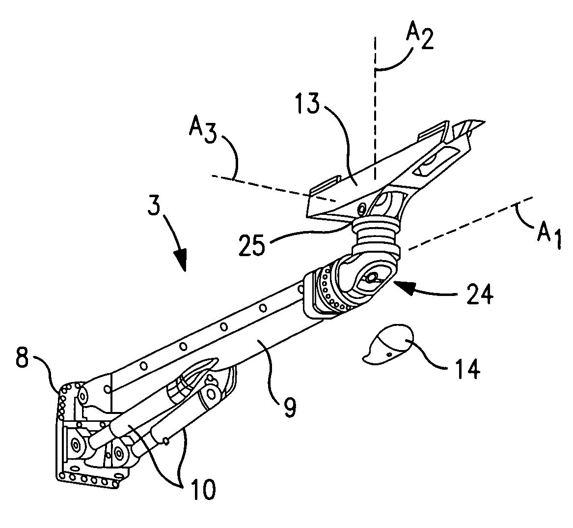
Figure 1 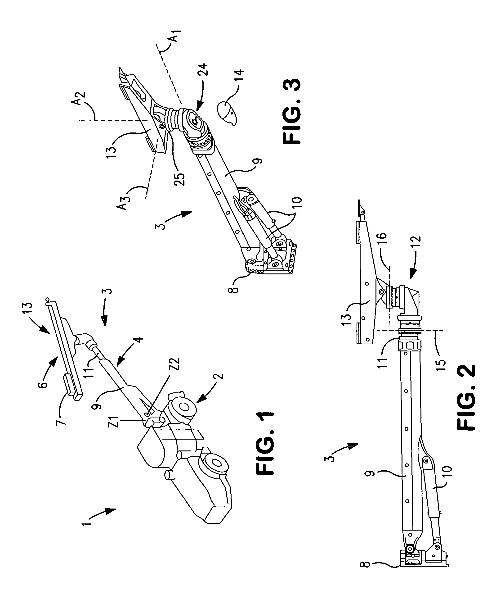
Figure 2 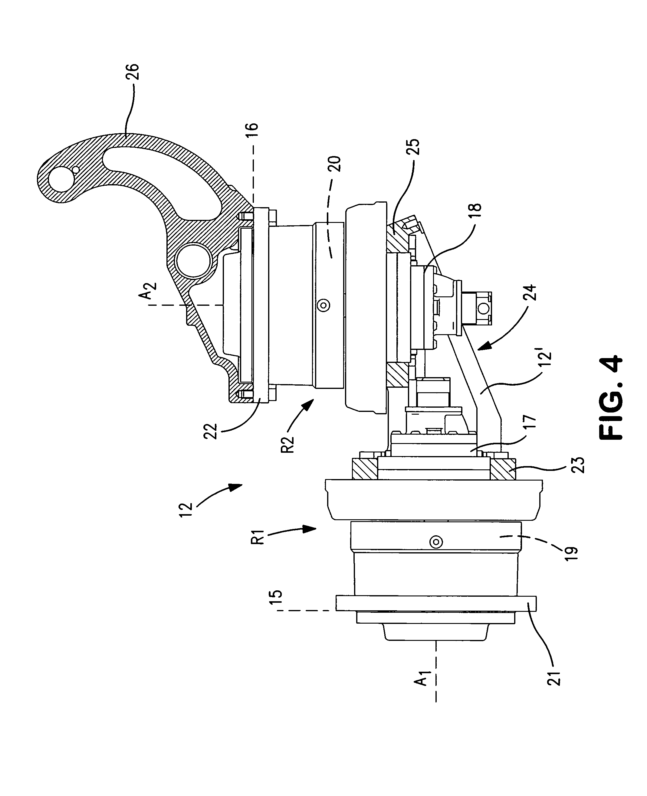
Figure 3
Abstract
Description
FIELD OF THE INVENTION
[0001] The invention concerns a rotation device for a boom of a mining or construction work rig. The invention also concerns a rig and a boom including such a rotation device.BACKGROUND OF THE INVENTION
[0002] From EP-B1-0 434 652, such a device is previously known in a telescopic boom arrangement, wherein a rotation motor at a rear end of a first boom portion is arranged to rotate a second boom portion. A rotation motor is positioned at the outer end of a second boom portion, which allows rotation of a feed beam for a rock drilling machine.
[0003] Through this arrangement, the rock drilling boom is maneuverable such that an operator can relatively easily position the feed beam in the desired position and direction with six degrees of freedom. The known device, however, makes it more difficult to make it possible to position with high precision, which is more and more essential for today's users. Because of the positioning and the arrangement of the first rotation m...
Examples
Embodiment Construction
[0017]In FIG. 1 reference numeral 1 in general concerns a rig in the form of a mining machine, which in this case is a machine for drilling of a blast hole and for applying rock reinforcements respectively. The mining machine 1 includes a carrier 2 having conventional driving arrangements and an operator cabin, wherein a boom device 3 is attached to the carrier. The boom device 3 includes a telescopic and liftable and lowerable boom 4, at the outer end of which being fastened equipment 13 for e.g. rock drilling, including a feeder 6 and a rock drilling machine 7. Z1 and Z2 indicate rotational axes for the boom device. Further rotational axes are described in the following.
[0018]FIG. 2 shows the boom device 3 in greater detail including a carrier attachment 8 and the telescopic boom, which includes a first boom portion 9 and a second boom portion 11 which is almost entirely retracted in the Figure (see the boom portions more drawn apart in FIG. 1). The boom 9, 11 is manoeuvred for li...