
End mill cutter
Patent Information
- Authority / Receiving Office
- US · United States
- Current Assignee / Owner
- Publication Date
- 2017-01-31
Smart Images
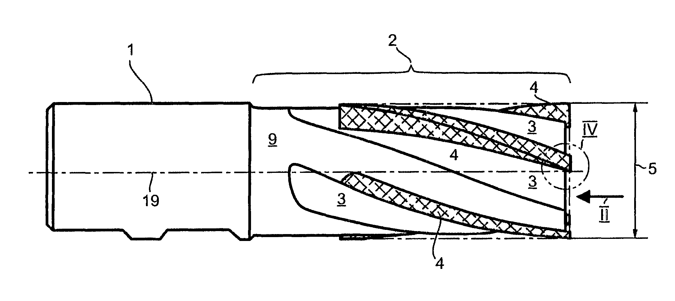
Figure 1 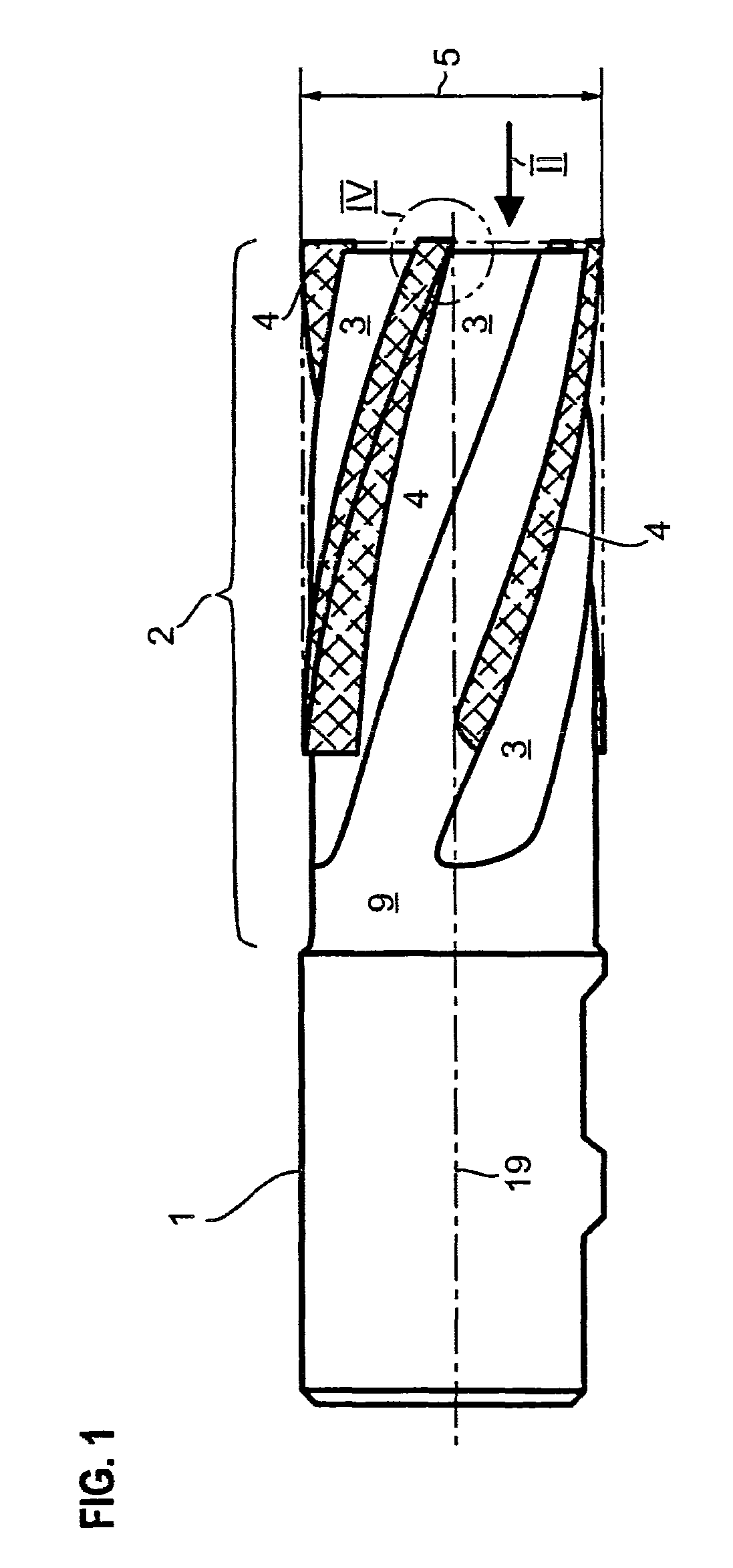
Figure 2 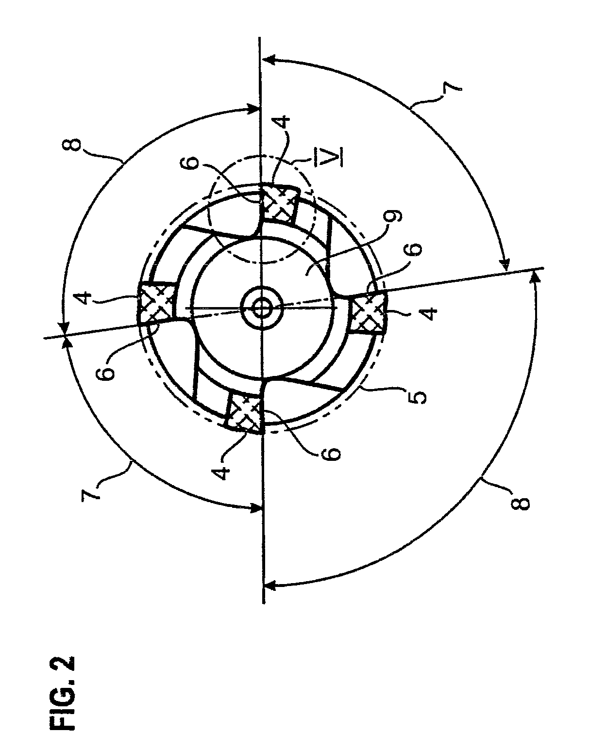
Figure 3
Abstract
Description
BACKGROUND OF THE INVENTION
[0001] Field of the Invention
[0002] The invention relates to a multi-edged end mill cutter. Such end mill cutters are normally used as conventional-milling cutters for the rough and finish machining of workpieces. For the machining, the workpieces are not always clamped in chucks of special machine tools. On the contrary, it is also normal practice for workpieces suspended during production from special transport and conveying equipment to be machined by means of such end mill cutters. For example, it is normal practice in the production of automobiles to suspend axle carriers or similar subassemblies from simple stirrups and to then machine them.
[0003] Description of the Related Art
[0004] As a result of a lack of stable clamping in a workpiece chuck, the workpiece is suspended only in a very unstable manner, such that the milling tool rotating in the opposite direction causes the workpiece suspended in an unstable manner to vibrate during the milling. This vi...
Examples
Embodiment Construction
[0030]The end mill cutter shown in side view in FIG. 1 consists of a clamping shank 1 for clamping in a tool chuck and a cutter region 2. The helical flutes 3 and the brazed-on cutting edge modules 4 can be seen in the cutter region 2. The cutter outside diameter 5 in the region of the cutting edge 6 can also be seen. It can be seen from the plan view of FIG. 2 that the cutter shown in the exemplary embodiment is a four-edged end mill cutter having four cutting edge modules 4. The pitch of the cutting edge modules and thus of the cutting edges 6 relative to one another is unequal. A small pitch angle 7 and a large pitch angle 8 alternate with one another in each case. In the exemplary embodiment, the small pitch angle 7 is 83° in each case, whereas the large pitch angle 8 is 97° in each case.
[0031]The cutting edge modules 4, which are brazed-on carbide strips in the exemplary embodiment, are brazed onto a parent body 9 made of hot-work steel. The flank 11 adjoins the cutting edge 6 ...