

GDI Engine Injector Flow Rate Testing Methods
AUG 28, 20259 MIN READ
Generate Your Research Report Instantly with AI Agent
PatSnap Eureka helps you evaluate technical feasibility & market potential.
GDI Injector Technology Background and Objectives
Gasoline Direct Injection (GDI) technology represents a significant advancement in internal combustion engine design, evolving from traditional port fuel injection systems to deliver fuel directly into the combustion chamber. Since its commercial introduction in the late 1990s, GDI has undergone substantial refinement, becoming a cornerstone technology in meeting increasingly stringent emissions regulations and fuel economy standards worldwide.
The evolution of GDI injector technology has been characterized by progressive improvements in precision, durability, and operational flexibility. Early GDI systems operated at relatively low pressures (50-100 bar), while modern systems commonly function at 200-350 bar, with advanced systems reaching up to 600 bar. This pressure escalation has enabled finer atomization of fuel, more precise control of injection timing, and multiple injection events per combustion cycle.
A critical component within this technological ecosystem is the GDI injector itself, which must withstand extreme operating conditions while maintaining nanometer-level precision. The injector's flow rate characteristics directly influence combustion efficiency, emissions formation, and engine performance across varying load conditions. Consequently, accurate measurement and characterization of injector flow rates have become paramount in both development and production quality control processes.
Current industry objectives for GDI injector technology focus on several key areas: enhancing atomization quality across wider operating ranges, improving spray pattern consistency under varying backpressure conditions, extending service life despite exposure to increasingly diverse fuel compositions, and maintaining precise flow rate characteristics throughout the injector's operational lifetime.
The testing methodologies for GDI injector flow rates have historically relied on steady-state measurement techniques adapted from port fuel injection systems. However, these approaches inadequately capture the dynamic behavior of modern multi-pulse injection strategies. This technological gap has spurred development of more sophisticated testing protocols capable of characterizing microsecond-level flow variations and shot-to-shot consistency.
Looking forward, the industry trajectory points toward even higher injection pressures (potentially exceeding 1000 bar), more complex injection strategies with up to eight discrete events per combustion cycle, and integration with advanced combustion modes such as homogeneous charge compression ignition (HCCI) and partially premixed combustion (PPC). These developments will necessitate corresponding advancements in flow rate testing methodologies to maintain pace with injector technology evolution.
The convergence of electrification trends with internal combustion technology has also created new requirements for GDI systems in hybrid powertrains, where transient operation and cold-start performance become increasingly critical. This evolution demands testing approaches that can accurately characterize injector performance under these specialized operating conditions.
Market Demand Analysis for Precise Flow Rate Testing
The global market for precise GDI (Gasoline Direct Injection) injector flow rate testing methods has experienced significant growth in recent years, driven primarily by increasingly stringent emission regulations and the automotive industry's push toward higher fuel efficiency. According to industry reports, the automotive fuel injection system market is projected to reach $92 billion by 2027, with GDI systems representing a substantial portion of this market.
The demand for precise flow rate testing methods stems from several key market factors. First, modern GDI engines require extremely accurate fuel delivery to maintain optimal air-fuel ratios across varying operating conditions. Even minor deviations in injector flow rates can lead to increased emissions, reduced performance, and potential engine damage. This precision requirement has created a specialized market for advanced testing equipment and methodologies.
Vehicle manufacturers face mounting pressure from regulatory bodies worldwide to reduce emissions while improving fuel economy. The European Union's Euro 7 standards, China's National 6 emissions regulations, and the United States' EPA Tier 3 requirements all demand unprecedented levels of precision in fuel delivery systems. This regulatory landscape has directly translated into market demand for more sophisticated testing capabilities.
The aftermarket and service sectors represent another significant market segment. As GDI systems age, injector performance can deteriorate due to carbon buildup and wear, necessitating accurate diagnostic and testing equipment for service centers. This maintenance market is expected to grow at a CAGR of 6.8% through 2028, creating sustained demand for accessible testing technologies.
From a geographical perspective, the Asia-Pacific region, particularly China and India, shows the highest growth potential for GDI testing equipment due to rapid automotive industry expansion and adoption of stricter emission standards. North America and Europe maintain strong market positions driven by their established automotive manufacturing bases and advanced research facilities.
The market also reveals a clear trend toward automated and integrated testing solutions that can evaluate multiple parameters simultaneously. End users increasingly demand systems that can test not only flow rate but also spray pattern, response time, and leakage in a single operation. This integration trend is reshaping product development roadmaps across the industry.
Cost sensitivity remains a significant market factor, with tier-2 and tier-3 suppliers seeking more affordable testing solutions that maintain acceptable precision levels. This has created a market segmentation between high-end laboratory-grade equipment and more practical production-line and service-center solutions.
Current Testing Methods and Technical Challenges
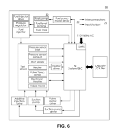
The current testing methods for GDI (Gasoline Direct Injection) engine injector flow rate can be categorized into static and dynamic testing approaches. Static testing involves measuring flow rates under constant pressure conditions, typically using specialized test benches that supply fuel at controlled pressures while measuring volumetric or mass flow over time. These methods provide baseline performance data but fail to capture real-world operating dynamics.
Dynamic testing methods more accurately simulate actual engine operating conditions by measuring injector performance during simulated or actual engine cycles. This includes pulse-width modulation testing, where injectors are activated with varying pulse durations to establish flow rate curves across different operating conditions. High-speed cameras and laser-based visualization techniques are increasingly employed to observe spray patterns and atomization characteristics in real-time.
Industry standard testing protocols such as ISO 4010 and SAE J1832 provide frameworks for injector testing, though these standards have struggled to keep pace with the rapid evolution of GDI technology. The latest testing equipment incorporates advanced sensors capable of microsecond-level measurement precision and computerized data acquisition systems that can process millions of data points per test cycle.
Despite these advancements, significant technical challenges persist in GDI injector flow rate testing. The ultra-high operating pressures of modern GDI systems (up to 350 bar) create substantial testing equipment requirements and safety concerns. Accurately replicating the complex in-cylinder conditions where injectors operate remains difficult, particularly regarding temperature gradients, back pressure variations, and combustion chamber aerodynamics.
Miniaturization of injector components has introduced measurement challenges, as internal flow passages now feature dimensions in the sub-millimeter range, making direct observation and measurement increasingly difficult. Carbon deposit formation, a common issue in GDI systems, significantly impacts flow characteristics over time, yet standardized methods for accelerated deposit testing remain underdeveloped.
The industry also faces challenges in correlating bench test results with actual engine performance. Laboratory measurements often fail to predict real-world behavior accurately, particularly regarding injector-to-injector variation and long-term durability. Additionally, the proprietary nature of many testing methodologies has hindered standardization efforts, with OEMs and tier suppliers often using different metrics and procedures to evaluate essentially identical performance parameters.
Emerging testing needs for alternative fuels compatibility and multi-pulse injection strategies have further complicated the testing landscape, requiring new methodologies and equipment capable of capturing increasingly complex injection events and fuel interactions.
Current Flow Rate Testing Solutions and Methodologies
01 Flow rate measurement and testing methods for GDI injectors
Various methods and devices are used to measure and test the flow rate of gasoline direct injection (GDI) engine injectors. These include specialized test benches, flow meters, and diagnostic equipment that can accurately determine injector flow characteristics under different operating conditions. These testing methods help ensure proper calibration and performance of injectors, which is critical for optimal engine operation, fuel efficiency, and emissions control.- Flow rate measurement and testing methods for GDI injectors: Various methods and devices for measuring and testing the flow rate of gasoline direct injection (GDI) engine injectors. These include specialized test benches, flow meters, and diagnostic systems that can accurately determine injector flow characteristics under different operating conditions. These measurement techniques help ensure proper calibration and performance verification of injectors to maintain optimal engine operation.
- Flow rate control systems for GDI injectors: Control systems designed to regulate and optimize the flow rate of fuel through GDI injectors. These systems typically involve electronic control units (ECUs) that adjust injection parameters based on engine operating conditions. Advanced control algorithms can compensate for variations in fuel pressure, temperature, and other factors to maintain precise fuel delivery, improving combustion efficiency and reducing emissions.
- Injector design improvements for optimized flow rate: Innovations in the physical design of GDI injectors to optimize flow rate characteristics. These include modifications to nozzle geometry, valve mechanisms, and internal flow paths to achieve better atomization and spray patterns. Design improvements focus on reducing flow restrictions, minimizing pressure losses, and ensuring consistent flow rates across the operating range of the engine.
- Fuel pressure regulation for flow rate management: Systems and methods for regulating fuel pressure to manage injector flow rates in GDI engines. These include high-pressure fuel pumps, pressure regulators, and pressure sensors that work together to maintain optimal fuel pressure for different engine operating conditions. Proper pressure regulation ensures consistent injector flow rates, which is critical for precise fuel metering and efficient combustion.
- Compensation strategies for injector flow rate variations: Methods and systems to compensate for variations in injector flow rates due to manufacturing tolerances, wear, or deposits. These include adaptive learning algorithms, individual injector correction factors, and real-time flow monitoring systems. Compensation strategies help maintain consistent engine performance over time by adjusting injection parameters to account for changes in injector flow characteristics.
02 Flow rate control systems for GDI injectors
Control systems are implemented to regulate and optimize the flow rate of GDI injectors based on engine operating conditions. These systems utilize electronic control units (ECUs) that adjust injection timing, duration, and pressure to achieve the desired flow rate. Advanced control algorithms can compensate for variations in fuel properties, engine temperature, and load conditions to maintain precise fuel delivery, improving combustion efficiency and reducing emissions.Expand Specific Solutions03 Injector design features affecting flow rate
The physical design of GDI injectors significantly impacts their flow rate characteristics. Key design elements include nozzle geometry, spray pattern, valve mechanisms, and internal flow passages. Innovations in these areas focus on optimizing atomization, reducing flow restrictions, and enhancing durability under high-pressure conditions. Advanced manufacturing techniques allow for precise orifice sizing and internal component geometries that deliver consistent flow rates across the operating range.Expand Specific Solutions04 Pressure-flow rate relationship in GDI systems
The relationship between fuel pressure and injector flow rate is critical in GDI systems. Higher injection pressures typically result in increased flow rates and improved fuel atomization. Modern GDI systems operate at significantly higher pressures than traditional port fuel injection systems, often exceeding 200 bar. Understanding and managing this pressure-flow relationship is essential for calibrating injection duration to achieve the desired fuel quantity across various engine operating conditions.Expand Specific Solutions05 Flow rate compensation and adaptation strategies
To maintain optimal engine performance over time, GDI systems employ various compensation and adaptation strategies for injector flow rates. These include algorithms that adjust for injector aging, deposit formation, and manufacturing variations. Some systems incorporate real-time feedback mechanisms that monitor combustion parameters and adjust injection parameters accordingly. These adaptive strategies help maintain consistent air-fuel ratios and combustion quality throughout the engine's operational life.Expand Specific Solutions
Key Industry Players in GDI Testing Equipment
The GDI Engine Injector Flow Rate Testing Methods market is currently in a growth phase, with increasing adoption across automotive manufacturers seeking to optimize fuel efficiency and emissions performance. The market size is estimated to be expanding at a steady rate due to stringent emission regulations globally. From a technical maturity perspective, the field shows varying levels of sophistication, with established players like Bosch, Continental Automotive, and Hyundai KEFICO leading innovation with advanced testing methodologies. Major automotive manufacturers including Hyundai, Ford, Kia, and BMW are investing significantly in proprietary testing technologies, while specialized equipment providers such as Michigan Custom Machines and Sonplas are developing increasingly precise measurement systems. The competitive landscape reflects a mix of OEM-developed solutions and third-party testing equipment providers, with collaboration between academic institutions and industry becoming increasingly important for technological advancement.
Hyundai Motor Co., Ltd.
Technical Solution: Hyundai has developed a comprehensive GDI injector flow rate testing system that integrates both static and dynamic measurement methodologies. Their approach utilizes a dual-chamber testing apparatus that simultaneously measures pre-injection and post-injection fuel quantities with precision flow meters capable of detecting variations as small as 0.2mm³ per injection event[1]. Hyundai's testing protocol incorporates variable pressure testing (50-250 bar) and multiple pulse width scenarios to simulate real-world driving conditions. Their system employs temperature-controlled testing environments to evaluate injector performance across the full operating temperature range experienced in modern engines. Hyundai has implemented machine learning algorithms to analyze flow rate patterns across millions of injection cycles, enabling predictive quality control and early detection of potential injector degradation[3]. Their methodology includes correlation testing between bench results and dynamometer validation to ensure laboratory measurements translate to actual engine performance.
Strengths: Exceptional measurement precision at both very short and long injection durations, comprehensive environmental condition testing, and advanced data analytics for quality control. Weaknesses: Higher equipment complexity requiring specialized maintenance, longer testing cycles for comprehensive evaluation, and significant calibration requirements.
Ford Global Technologies LLC
Technical Solution: Ford has developed a sophisticated GDI injector flow rate testing methodology that combines traditional volumetric measurement with advanced real-time monitoring systems. Their approach utilizes a closed-loop testing environment where fuel is circulated through precision measurement chambers under carefully controlled pressure conditions ranging from 50 to 300 bar[2]. Ford's system incorporates multiple temperature sensors and pressure transducers to continuously monitor testing conditions, ensuring consistency across test cycles. Their methodology includes both static flow measurement for calibration verification and dynamic pulse testing that simulates actual engine operating conditions with injection durations as short as 0.2ms. Ford has implemented a proprietary digital signal processing system that analyzes injection patterns across multiple frequencies to detect anomalies in injector performance that might not be apparent in standard volumetric tests[4]. Their testing protocol includes evaluation of injector-to-injector variation within production batches, enabling statistical process control for manufacturing quality assurance. Ford's system also incorporates accelerated life testing capabilities, subjecting injectors to equivalent of 150,000 miles of operation to predict long-term performance and durability.
Strengths: Excellent correlation between test results and real-world performance, comprehensive quality control capabilities, and ability to detect subtle performance variations between production batches. Weaknesses: Complex equipment setup requiring specialized technical expertise, higher initial investment costs, and longer testing cycles for comprehensive evaluation.
Critical Patents and Research in Flow Rate Measurement
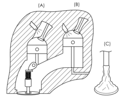
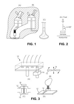
Method for maximizing the formation of deposits in injector nozzles of GDI engines
PatentWO2018002610A1
Innovation
- A method to maximize deposit formation in GDI engine injector nozzles by simulating severe conditions through controlled engine speed and load variations, high nozzle temperatures, and moderate fuel flow rates, allowing for automated and unsupervised testing to quickly assess fuel's deposit-forming tendencies.
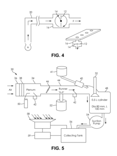
Evaluation of the delivery and effectiveness of engine performance chemicals and products
PatentActiveUS20170114716A1
Innovation
- A method and system for evaluating the delivery and effectiveness of engine performance chemicals and products for reducing intake valve deposits, utilizing a controlled environment with simulated engine conditions to quantify improvements, including adjustable parameters like air-fuel ratio, temperature, and oscillation frequency, and employing three approaches to introduce cleaners: airstream addition, suction-based distribution, and fuel additive application.
Calibration Standards and Accuracy Requirements
Accurate calibration standards are fundamental to the reliability of GDI injector flow rate testing methods. The industry has established several calibration protocols that must be adhered to for ensuring measurement consistency across different testing environments. ISO 4113 provides the primary reference standard for calibration fluids used in GDI injector testing, specifying the physical properties that test fluids must maintain to ensure comparable results. These properties include viscosity ranges of 1.9-2.1 mm²/s at 40°C and density specifications of 810-820 kg/m³ at 15°C.
For flow rate measurement devices, calibration accuracy requirements typically demand ±0.5% full-scale accuracy for mass flow meters and ±0.3% for volumetric measurement systems. These stringent requirements ensure that measurement variations remain within acceptable tolerances for engineering decisions. Calibration frequency is another critical aspect, with most standards recommending recalibration every 6-12 months depending on usage intensity and environmental conditions.
Temperature control during calibration represents a significant factor affecting measurement accuracy. Standards specify that calibration environments must maintain temperature stability within ±1°C throughout the calibration process, with test fluid temperature controlled to within ±0.5°C of the specified reference temperature. This level of control is necessary because fluid viscosity changes approximately 2-3% per degree Celsius, directly impacting flow characteristics.
Traceability to national or international measurement standards is mandatory for all calibration equipment. NIST in the United States, PTB in Germany, and similar organizations in other countries provide reference standards against which all calibration equipment must be verified. Documentation of this traceability chain forms an essential part of the calibration process and subsequent test validation.
Uncertainty analysis has become increasingly important in modern calibration standards. The latest requirements mandate that testing facilities document all sources of measurement uncertainty, including instrument accuracy, environmental variations, and procedural factors. The combined standard uncertainty must be calculated according to GUM (Guide to the Expression of Uncertainty in Measurement) principles, with expanded uncertainty (typically k=2, representing a 95% confidence interval) not exceeding 1.2% for critical applications.
Cross-verification between different measurement methods is now recommended as best practice. This involves comparing results from mass flow, volumetric flow, and time-based measurement approaches to identify systematic errors that might not be apparent within a single measurement methodology. Discrepancies exceeding 1% between methods trigger investigation requirements under current standards.
Environmental Impact of Testing Procedures
The environmental impact of GDI engine injector flow rate testing methods has become increasingly significant as automotive manufacturers face stricter emissions regulations worldwide. Traditional testing procedures often involve the use of specialized fluids that contain hydrocarbons and other potentially harmful chemicals. When these fluids are disposed of improperly, they can contaminate soil and water sources, leading to long-term environmental damage. Furthermore, the energy consumption associated with operating testing equipment contributes to the carbon footprint of automotive development processes.
Recent studies indicate that a standard injector testing facility may generate between 5-10 gallons of waste fluid daily, amounting to thousands of gallons annually for larger operations. These fluids typically contain calibration compounds, cleaning solvents, and test fuels that require specialized disposal methods. The environmental cost of manufacturing these test fluids must also be considered in the overall ecological assessment of testing procedures.
Air quality represents another environmental concern, as volatile organic compounds (VOCs) are released during the testing process. Without proper ventilation and filtration systems, these emissions can contribute to local air pollution and potentially affect the health of laboratory personnel. Some advanced testing facilities have implemented closed-loop systems that capture and recycle test fluids, significantly reducing both waste generation and VOC emissions.
Water usage presents an additional environmental challenge, particularly in regions facing water scarcity. Cooling systems for test equipment and cleaning processes can consume substantial volumes of water. Innovative facilities have begun implementing water recycling systems that can reduce consumption by up to 60%, though these systems require significant initial investment.
The carbon footprint of testing operations extends beyond direct energy consumption to include the environmental impact of manufacturing specialized testing equipment. Life cycle assessments of testing facilities indicate that the embodied carbon in precision testing apparatus can be substantial, with specialized components often requiring energy-intensive manufacturing processes and rare materials.
Forward-thinking companies are now developing more sustainable testing methodologies that utilize biodegradable test fluids, energy-efficient equipment, and comprehensive waste management protocols. These approaches not only reduce environmental impact but often result in cost savings through reduced waste disposal fees and lower energy consumption. Regulatory bodies in Europe and North America have begun incorporating environmental impact assessments into their certification requirements for testing facilities, accelerating the adoption of greener testing practices throughout the industry.
Unlock deeper insights with PatSnap Eureka Quick Research — get a full tech report to explore trends and direct your research. Try now!
Generate Your Research Report Instantly with AI Agent
Supercharge your innovation with PatSnap Eureka AI Agent Platform!