

Spetacle frame spring hinge structure
A technology of spring hinges and spectacle frames, which is applied in glasses/goggles, optics, instruments, etc., and can solve problems such as fast wear of parts, performance failures, and friction
- Summary
- Abstract
- Description
- Claims
- Application Information
AI Technical Summary
Problems solved by technology
Method used
Image

Examples
Embodiment Construction
[0056] In order to further elaborate the technical means and effects adopted by the present invention to achieve the predetermined purpose, please refer to the following detailed description and accompanying drawings of the present invention. It is believed that the purpose, characteristics and characteristics of the present invention should be able to gain a deep and specific understanding from this , however, the accompanying drawings are provided for reference and illustration only, and are not intended to limit the present invention.
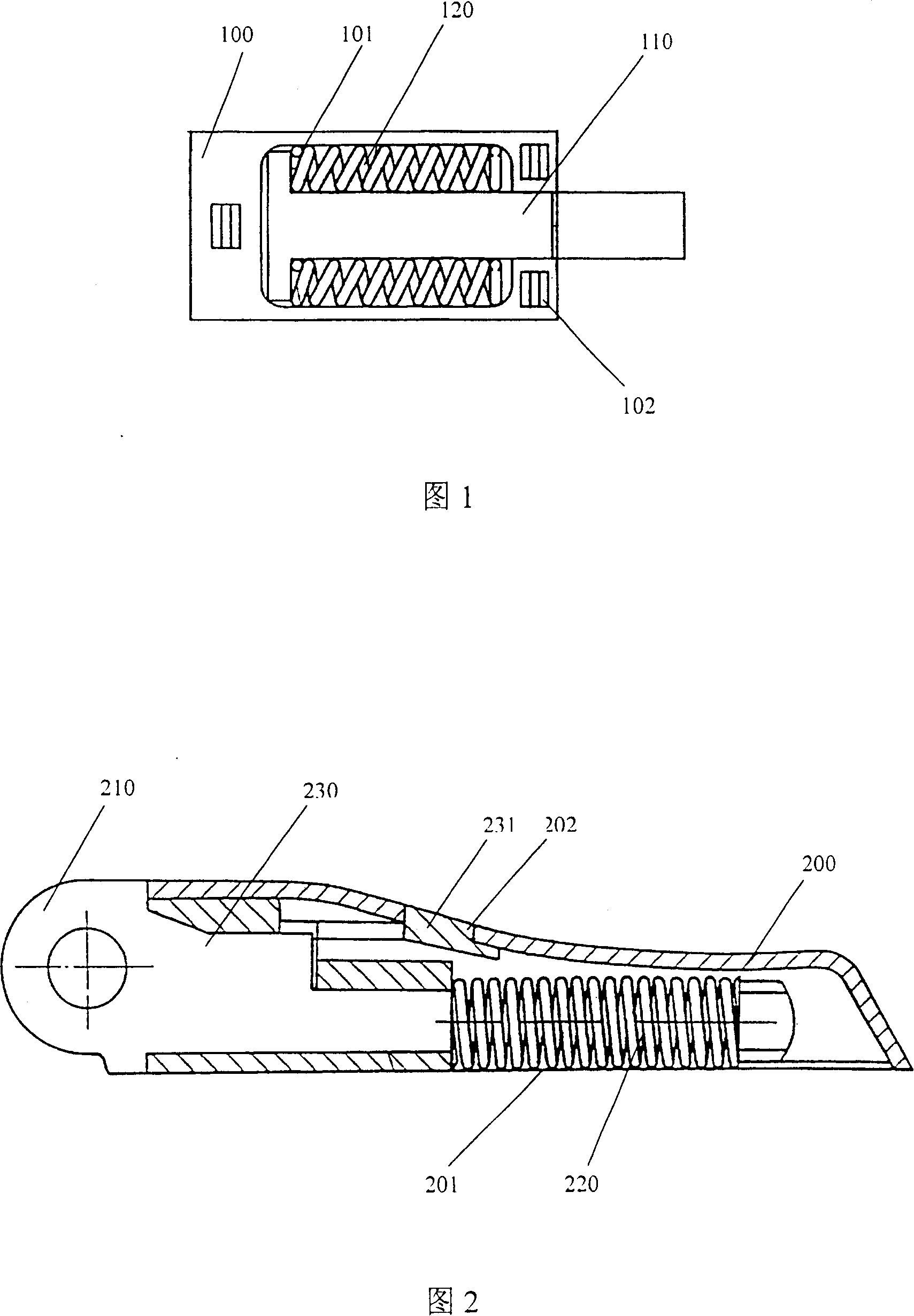
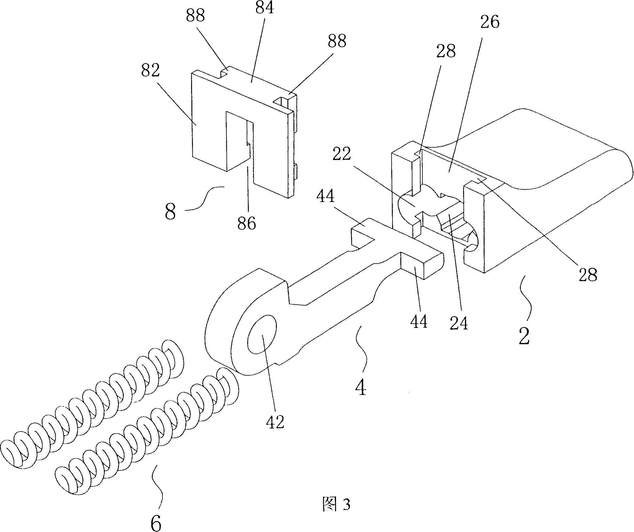
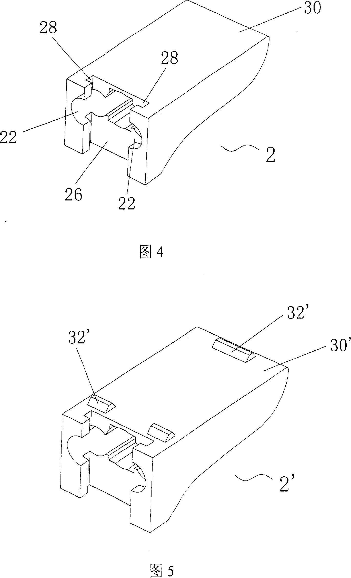
[0057] As shown in FIG. 3 , the present invention provides a spring hinge structure for a spectacle frame, which includes a spring box 2 , a joint 4 , a pair of springs 6 and a packaging element 8 . Please refer to Fig. 4 at the same time, the spring box 2 can be made of various metal materials, such as zinc white copper, titanium metal or bronze, phosphor bronze, etc. The pair of springs 6, a longitudinal guide groove 24 that is arranged be...
PUM
 Abstract
Description
Claims
Application Information