Composite thermal insulation concrete shear wall

A technology of concrete shear wall and thermal insulation concrete, applied in the direction of walls, building components, buildings, etc., can solve the problems of inability to satisfy comfort, poor overall performance, etc., and achieve the goal of improving thermal insulation efficiency, improving construction quality, and reducing cost. Effect

Inactive Publication Date: 2008-12-10
陈信孚 +1
View PDF5 Cites 1 Cited by
  • Summary
  • Abstract
  • Description
  • Claims
  • Application Information

AI Technical Summary

Problems solved by technology

In order to save materials, our country has also invented concrete perforated slab houses. Practice has proved that the overall performance of this house is poor and cannot meet the comfort requirements.

Method used


Image

  • Composite thermal insulation concrete shear wall
  • Composite thermal insulation concrete shear wall
  • Composite thermal insulation concrete shear wall

Examples


Embodiment 1

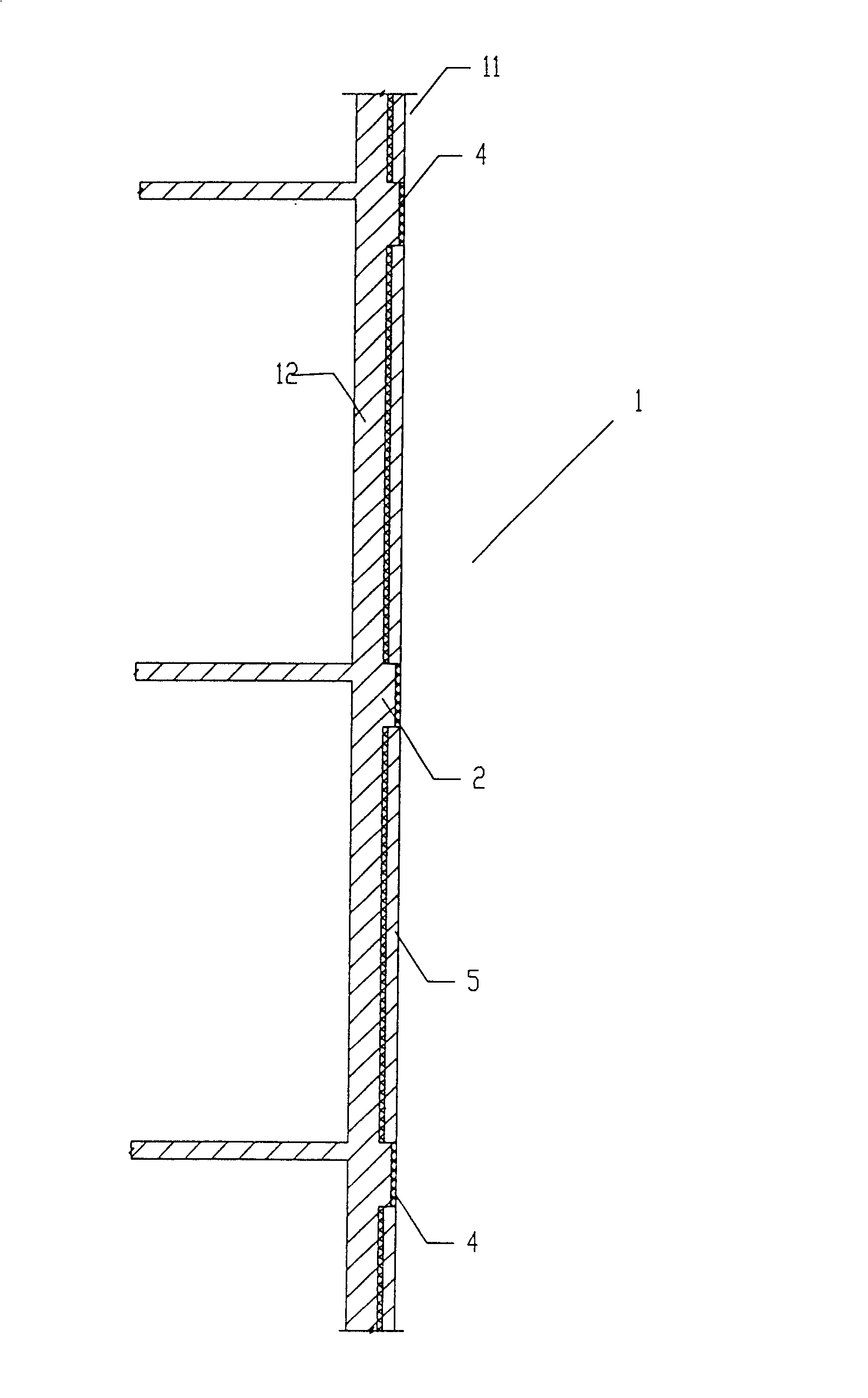
[0028] see figure 1 , a composite thermal insulation concrete shear wall, including a wall 1 and a connecting beam 2, the wall 1 is composed of a prefabricated thermal insulation concrete wall 11 and a cast-in-place concrete wall 12, and the prefabricated thermal insulation concrete wall 11 is an inner surface cladding Concrete slab 5 with thermal insulation material layer 4, thermal insulation material layer 4 in prefabricated thermal insulation concrete wall 11 and cast-in-place concrete wall 12 are compositely poured into one body; It is integrated with the upper and lower cast-in-place concrete walls 12, and the outer end surface of the connecting beam 2 is covered with a layer of thermal insulation material 4.

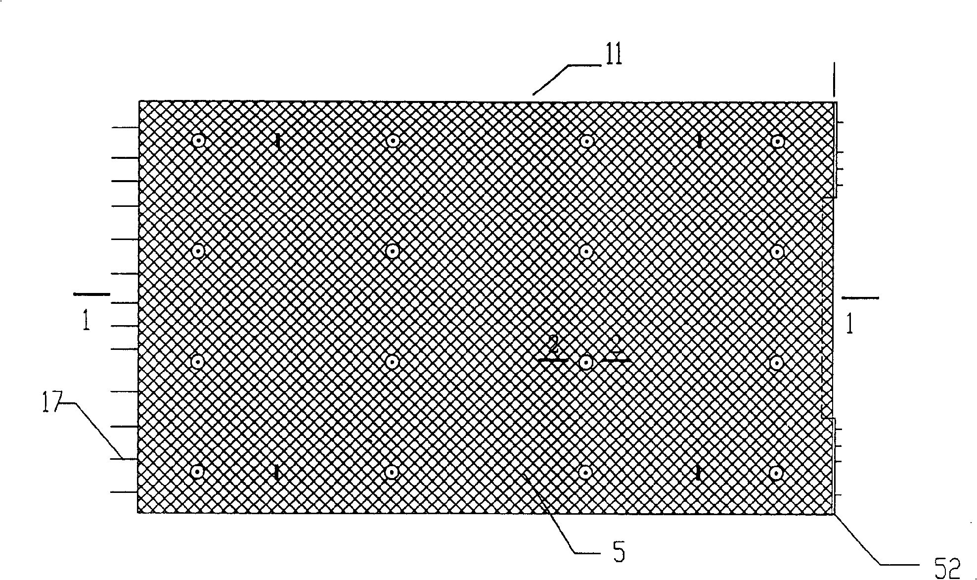
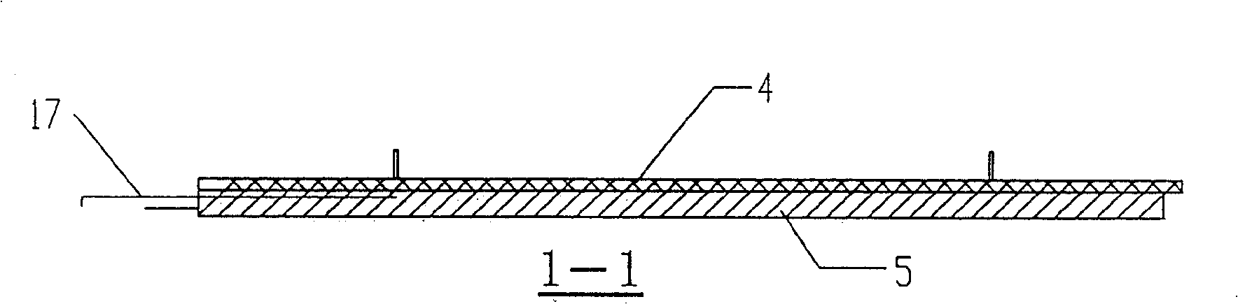
[0029] see figure 2 , 3, 4, internal screw holes 16 are embedded at intervals in the prefabricated thermal insulation concrete wall 11, the screw 15 is inserted into the internal screw hole screw 16, and protrudes outside the insulation material layer 4 of the p...


PUM


Abstract

The present invention relates to a compound heat-insulating concrete shear wall. Said heat-insulating concrete shear wall is made up by using heat-insulating material as main material. Said shear wall includes wall body and connecting beam. The described wall body includes prefabricated heat-insulating concrete wall body and cast-in-place concrete wall body, said prefabricated heat-insulating concrete wall body is a concrete plate whose one side surface is covered with a layer of heat-insulating material, and in the prefabricated heat-insulating concrete wall body interior several steel components are spaced and embedded, one end of every steel component is placed in the concrete plate interior and its another end is projected from said heat-insulating material layer of the prefabricated heat-insulating concrete plate. Said invention also provides its concrete assembly and construction method and steps.

Description

technical field [0001] The invention relates to a concrete house, in particular to a composite thermal insulation concrete shear wall. Background technique [0002] Most of the existing high-rise buildings are concrete houses, including frame-shear wall concrete houses, frame-tube concrete houses, full shear wall concrete houses and tube-tube wall concrete houses. [0003] Most of the existing concrete houses use cast-in-place concrete structure systems, which consume a lot of wood to make formwork, which will seriously consume forest resources and affect the environment and climate. [0004] The cast-in-place concrete house structure is all constructed on site, with high manual labor intensity, low factory level, many processes, high cost and long construction period. [0005] Existing building energy-saving technologies are developed on the premise of not changing the existing building structure system. In terms of form, there are two types of external wall thermal insul...

Claims


Application Information

Patent Timeline
Patent Type & Authority Patents(China)
IPC IPC(8): E04B2/00E04B2/84E04B1/00E04B1/74
Inventor 陈信孚曲萍
Owner 陈信孚
Why Eureka
Try Eureka