

Data transfer apparatus, and data transfer method and program
A technology of data transmission and transmission unit, which is applied in the input/output process of data processing, electrical digital data processing, instruments, etc., to achieve the effects of improving transmission efficiency, improving use efficiency, and improving data transmission efficiency
- Summary
- Abstract
- Description
- Claims
- Application Information
AI Technical Summary
Problems solved by technology
Method used
Image

Examples
Embodiment approach 1
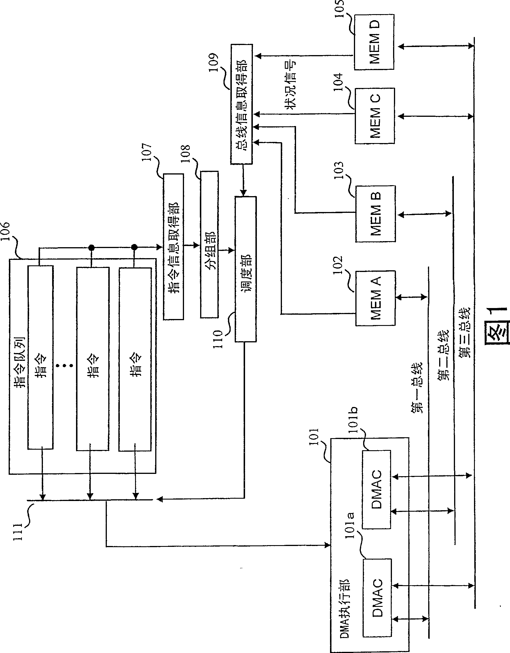
[0068] FIG. 1 is a block diagram showing the configuration of a DMA data transfer device (hereinafter referred to as a data transfer device) in Embodiment 1 of the present invention. The data transmission device includes a DMA execution unit 101, a memory A102, a memory B103, a memory C104, a memory D105, an instruction queue 106, an instruction information acquisition unit 107, a grouping unit 108, a bus information acquisition unit 109, a scheduling unit 110, and a selector 111.
[0069] The DMA execution unit 101 has a DMAC101a and a DMAC101b, and executes DMA data transfer between the memory A102, the memory B103, the memory C104, and the memory D105. The first bus connected to the memory A102, the second bus connected to the memory B103, and the third bus connected to the memory C104 and the memory D105 are independent buses.
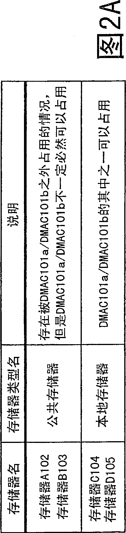
[0070] FIG. 2A is an explanatory diagram of the memory A102 to the memory D105. As shown in the figure, the memory A102 and the memory B103 are c...
Embodiment approach 2
[0087] 7 is a block diagram showing the configuration of a DMA data transfer device according to Embodiment 2 of the present invention. This DMA data transfer device is included in a device that processes a frame representing an image for each rectangular area, and differs from the data transfer device shown in FIG. 1 in that a command changing unit 201 is added. Hereinafter, the description of the same points will be omitted, and the description will focus on the different points.
[0088] The command changing unit 201 analyzes the attribute of the command acquired by the command information acquiring unit 107 and the bus information acquired by the bus information acquiring unit 109, and divides any command held in the command queue 106 into two or more commands.
[0089] FIG. 8 is a diagram showing a first example of changing a command by the command changing unit 201 . In the figure, command 1 is the head command of the command queue 106, and is the data of the rectangula...
Embodiment approach 3
[0093] FIG. 11 is a block diagram showing the configuration of a DMA data transfer device according to Embodiment 3 of the present invention. Compared with the DMA data transfer device shown in FIG. 7, this DMA data transfer device has a DMA execution unit 301 instead of the DMA execution unit 101, a new instruction retention unit 302 and a selector 303, and a scheduling unit 310 instead of the scheduling unit. 110, differ in these respects. The description of the same points will be omitted below, and the description will focus on the different points.
[0094] The DMA execution unit 301 has a DMAC301a and a DMAC301b. In addition to the function of the DMAC 101a, the DMAC 301a is configured to output a command instructing the remaining data transfer to the command holding unit 302 during DMA data transfer. The same applies to DMAC301b.
[0095] Command holding unit 302 temporarily holds commands output from DMAC 301a or DMAC 301b.
[0096] The selector 303 inputs the comm...
PUM
 Abstract
Description
Claims
Application Information