LCD unit matrix and LCD device embodying the matrix

A liquid crystal unit, liquid crystal display technology, applied in electrical components, static indicators, optics, etc., can solve the problems of increased cost, motion blur, extra cost of the second gate driver, etc., and achieve the effect of increased cost

Active Publication Date: 2010-03-10
NANJING CEC PANDA LCD TECH
View PDF7 Cites 0 Cited by
  • Summary
  • Abstract
  • Description
  • Claims
  • Application Information

AI Technical Summary

Problems solved by technology

[0014] The liquid crystal display is a sample-and-hold display device, and its problem is that the residual image of the previous frame produces motion blur
The advantage of this method is that the time for image data charging is guaranteed, and the disadvantage is that the cost of the second gate driver is increased, which increases the cost

Method used


Image

  • LCD unit matrix and LCD device embodying the matrix
  • LCD unit matrix and LCD device embodying the matrix
  • LCD unit matrix and LCD device embodying the matrix

Examples


Embodiment Construction

[0044] The present invention will be further described below in conjunction with the accompanying drawings and embodiments.

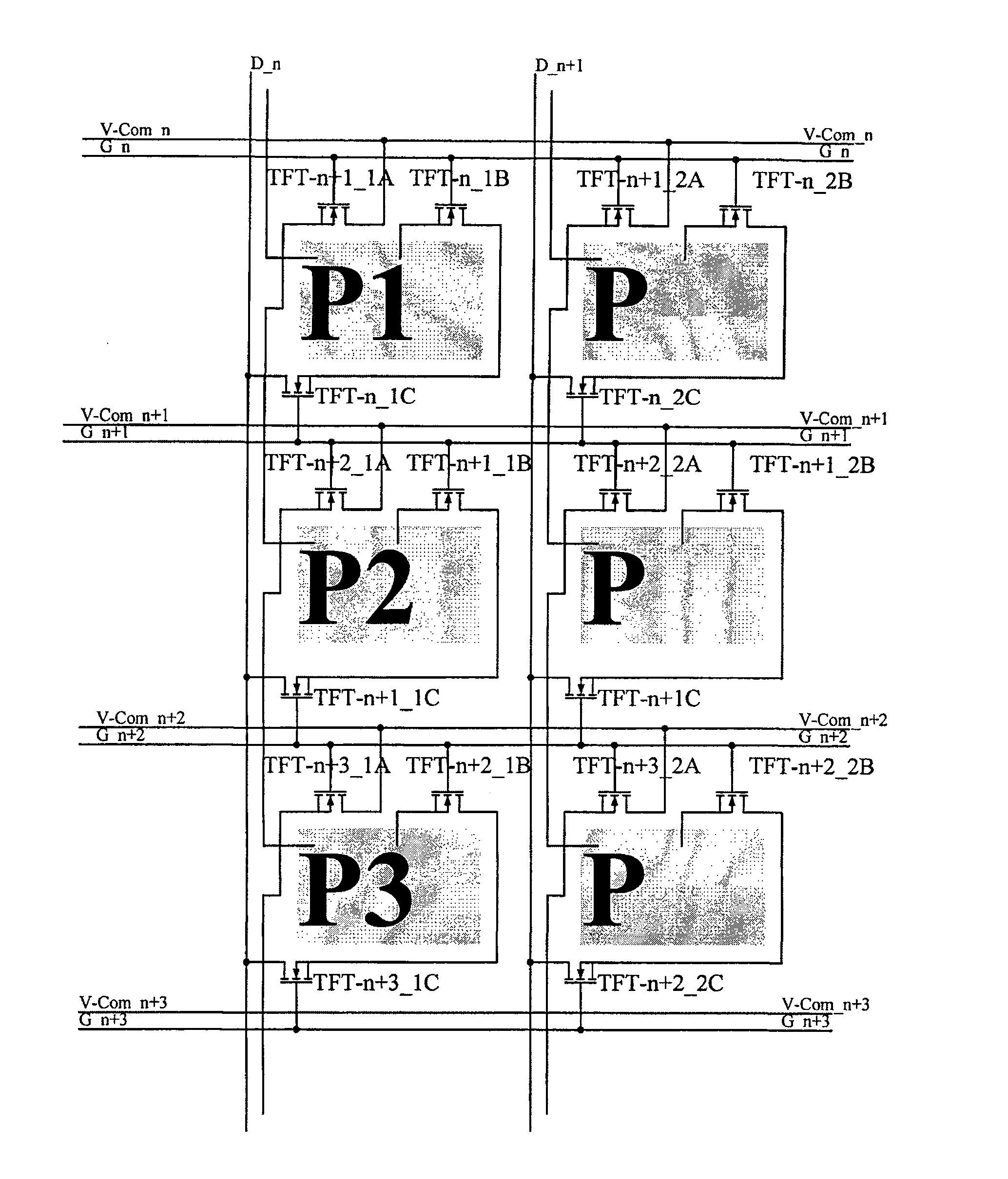
[0045] figure 2 The structure of the liquid crystal cell matrix of the present invention is shown. See figure 2, the liquid crystal cell matrix P1 includes: the scan line G_n (n is a natural number) that provides the scan signal; the data line D_n that provides the data signal; the common line V-Com_n that provides the common voltage; the gate of the thin film transistor TFT-n+1_1A is connected to the scan Line G_n, the source is connected to the common line V-Com_n, the drain is connected to the pixel electrode of the liquid crystal cell matrix P2, and the thin film transistor TFT-n+1_1A responds to the nth row of scanning lines and provides a common voltage to the pixel electrode; the thin film transistor TFT -n_1B The gate is connected to the scan line G_n, the source is connected to the drain of the thin film transistor TFT-n_1C, and the drain i...


PUM


Abstract

The present invention discloses a liquid crystal unit matrix and a liquid crystal display device comprising the same, which not only ensures the time of inputting image data, but also saves the cost of a second grid driver. The technical proposal is that: the liquid crystal unit matrix comprises a scan line for providing a scan signal, a data line for providing a data signal, a common line for providing a common voltage, a pixel electrode, a first thin film transistor responsive to the scan line of a current row, a second thin film transistor responsive to the scan line of the next row, wherein, a source electrode of the second thin film transistor is used for receiving the data signal; a third thin film transistor responsive to the scan line of the current row, the source electrode of thethird thin film transistor is connected with the drain of the second thin film transistor, wherein, the data signal of the data line is provided to the pixel electrode of the current row by the second thin film transistor and the third thin film transistor, the common voltage of the common line is provided to the pixel electrode of the next row by the first thin film transistor. The liquid crystal unit matrix and the liquid crystal display device are application in the liquid crystal display device filed.

Description

technical field [0001] The present invention relates to a liquid crystal display device, in particular to a liquid crystal display device for eliminating motion blur caused by a residual image of a previous frame. Background technique [0002] Liquid crystals have the characteristics of birefringence, and under different electric fields, there will be different arrangements. Liquid crystal displays use liquid crystal light valves to control light transmittance, thereby displaying images. Traditional liquid crystal display structure such as figure 1 As shown, it includes: a liquid crystal display panel 10, which has a gate driver 20 for driving the scanning line GL of the liquid crystal display panel 10; a data driver 30 for driving the data line DL of the liquid crystal display panel 10; and a timing controller 40 , for controlling the gate driver 20 and the data driver 30 . [0003] The liquid crystal display panel 10 includes a plurality of liquid crystal cell matrixes,...

Claims


Application Information

Patent Timeline
Patent Type & Authority Patents(China)
IPC IPC(8): G02F1/1362H01L27/12G09G3/36
Inventor 沈奇奇朱云
Owner NANJING CEC PANDA LCD TECH
Why Eureka
Try Eureka