

LCD device
A liquid crystal display device, liquid crystal display panel technology, applied in static indicators, nonlinear optics, instruments, etc., to achieve the effect of eliminating motion blur, easy to implement, and reducing aperture ratio
- Summary
- Abstract
- Description
- Claims
- Application Information
AI Technical Summary
Problems solved by technology
Method used
Image

Examples
Embodiment 1
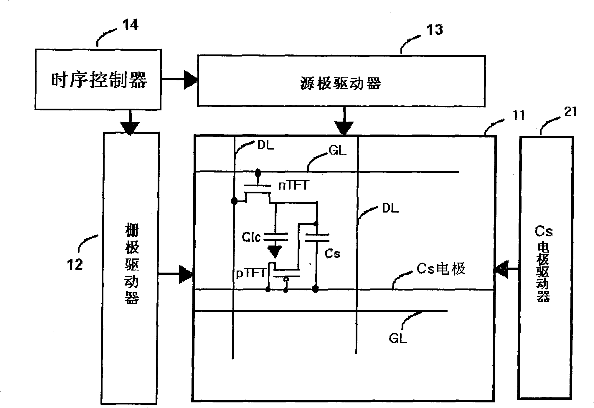
[0032] figure 2 A schematic structural diagram of a liquid crystal display according to Embodiment 1 of the present invention is shown; image 3 for correspondence figure 2 The schematic diagram of the drive.
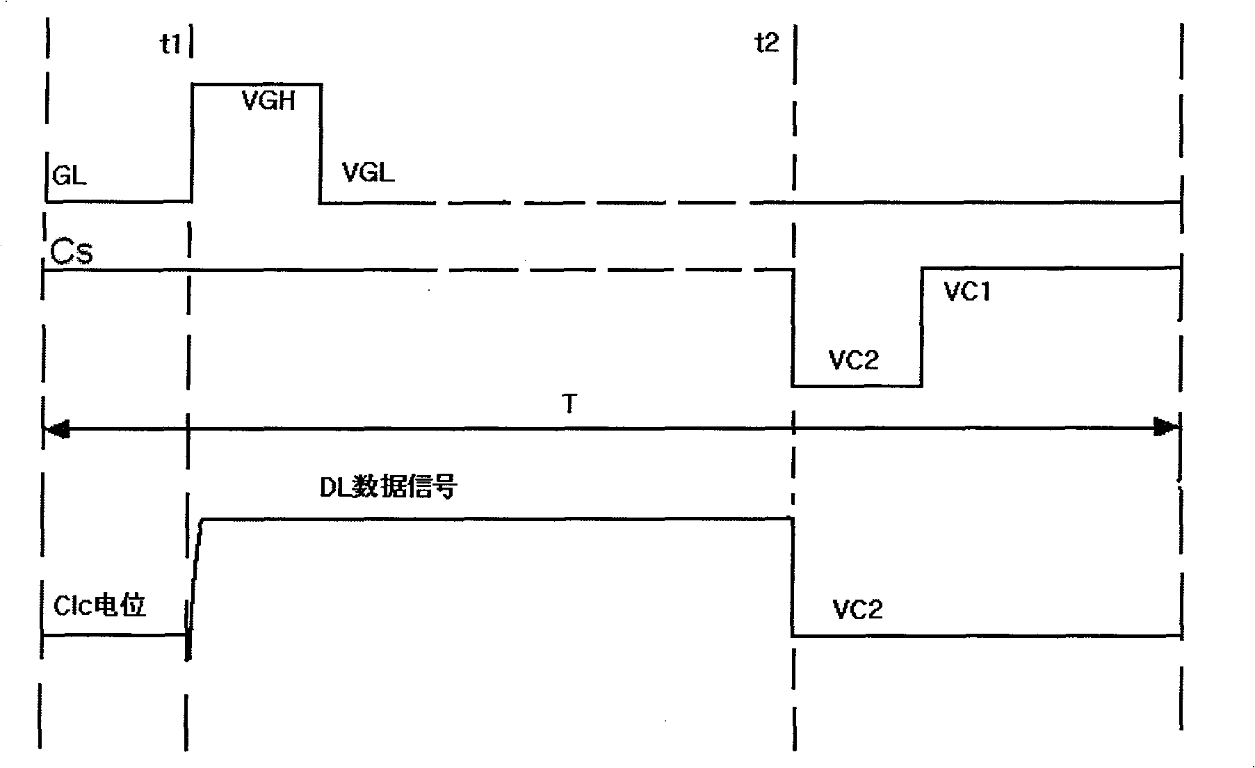
[0033] See figure 2 and image 3 , on the basis of the existing liquid crystal display structure, a pTFT is added to the Cs electrode of the liquid crystal cell part as a second TFT, the gate and source of the second TFT are connected to the Cs electrode line, and the drain is connected to the Cs capacitor. Its driving principle is as image 3 As shown, within the time T of one frame, the GL in the liquid crystal cell is gated by the VGH pulse output by the gate driver 12 at time t1. At this time, the data signal on DL charges Clc, and when the voltage on GL changes When it is VGL, the TFT on GL is turned off, and the voltage difference across Clc is maintained by the Cs capacitor; therefore, from t1 to t2, the liquid crystal unit displays the gray scale require...
Embodiment 2
[0035] Figure 4 A schematic structural diagram of a liquid crystal display according to Embodiment 2 of the present invention is shown; Figure 5 yes Figure 4 Schematic diagram of the drive for the illustrated embodiment.
[0036] See Figure 4 and Figure 5 , on the basis of the existing liquid crystal display structure, an nTFT is added to the Cs electrode of the liquid crystal cell part as a second TFT, the gate and source of the second TFT are connected to the Cs electrode line, and the drain is connected to the Cs capacitor. Its driving principle is as Figure 5 As shown, within the time T of one frame, the GL in the liquid crystal cell is gated by the VGH pulse output by the gate driver 12 at time t1. At this time, the data signal on DL charges Clc, and when the voltage on GL changes When it is VGL, the TFT on GL is turned off, and the voltage difference across Clc is maintained by the Cs capacitor; therefore, from t1 to t2, the liquid crystal unit displays the gr...
Embodiment 3
[0038] Figure 6 It is a structural schematic diagram of a liquid crystal display according to Embodiment 3 of the present invention.
[0039] See Figure 6 , on the basis of the existing liquid crystal display structure, an nTFT is added to the Cs electrode of the liquid crystal cell part as the second TFT, the gate and source of the second TFT are connected to the Cs electrode line, the drain is connected to the Cs capacitor, and the gate The pole line GL and the Cs electrode line are driven by a dual gate driver 22 . In Embodiment 2, the gate line GL is driven by a gate driver, and the Cs electrode line is driven by a Cs electrode driver; Figure 5 It can be seen from the driving principle of the gate line and the Cs electrode line that the driving of the gate line and the Cs electrode line is also a second-order drive; therefore, in this embodiment, the gate driver and the Cs electrode in Embodiment 2 are further integrated driver is a dual gate driver 22, i.e. Figure...
PUM
 Abstract
Description
Claims
Application Information