Flash tank for economizer refrigeration systems

A refrigeration system and capacity expansion box technology, which is applied in the direction of refrigerators, refrigeration components, refrigeration and liquefaction, etc., can solve the problems of long maintenance and repair, high price, etc., and achieve the effect of improving operation and performance, simple structure and efficient expansion

Inactive Publication Date: 2007-08-15
YORK INT CORP
View PDF2 Cites 10 Cited by
  • Summary
  • Abstract
  • Description
  • Claims
  • Application Information

AI Technical Summary

Problems solved by technology

This complex structure is expensive and time-consuming to manufacture, maintain and repair

Method used


Image

  • Flash tank for economizer refrigeration systems
  • Flash tank for economizer refrigeration systems
  • Flash tank for economizer refrigeration systems

Examples


Embodiment Construction

[0026] The subject matter contemplated by the present invention relates to a system and method for increasing the efficiency and capacity of a refrigeration system employing an economizer. The system and method can be used with any type of compressor, but is particularly suitable for use with screw compressors because screw compressors can be conveniently incorporated with an economizer.

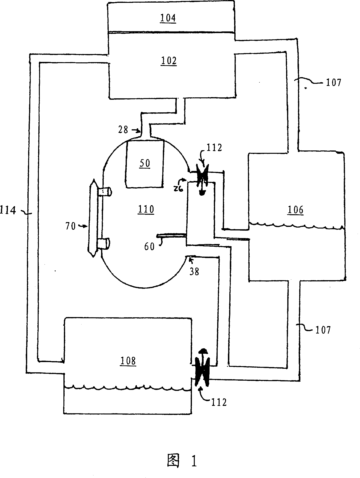
[0027] Referring first to Figure 1, there is shown a conventional refrigeration system 100 incorporating the economizer circuit of the present invention. As shown in this figure, the refrigeration system 100 includes a compressor 102 , a motor 104 , a condenser 106 , an evaporator 108 and an economizer expansion box 110 . The conventional refrigeration system 100 also includes other components not shown in FIG. 1 . For ease of explanation, the drawings are simplified and these components are intentionally omitted.

[0028] Compressor 102 compresses the refrigerant vapor and sends the vapor...


PUM


Abstract

A flash tank configuration for an economizer includes an upper baffle (50) and a lower baffle (60) configured and arranged within the flash tank (110) so as to separate the liquid and gas phases of intermediate pressure refrigerant, and to convey each phase to other components in the refrigeration system (100). The flash tank (110) has a generally cylindrical shape, and is dimensioned so as to provide adequate internal volume for expansion of refrigerant to a desired pressure, separation of the resulting refrigerant gas and refrigerant liquid phases, and temporary storage of the refrigerant phases before conveying the liquid phase to the main refrigerant line (107) between the condenser (106) and the evaporator (108), and returning the gas phase to the compressor (102).

Description

technical field [0001] The present invention relates to controlling the capacity and efficiency of a refrigeration system, in particular to a flash tank economizer for improving the performance of a refrigeration system. As will be explained below, the present invention includes an expansion tank economizer structure which utilizes a system of internal baffles to expand the liquid refrigerant, allowing the refrigerant gas produced by the expansion to be separated from the remaining liquid refrigerant and sent to other components of the refrigeration system. The refrigerant gas and liquid are temporarily stored beforehand. Background technique [0002] A conventional compression refrigeration system consists of the following components: an evaporator for heat exchange between the cooled medium and the refrigerant; a compressor that sucks the low-pressure gas refrigerant generated in the evaporator and compresses the gas to a suitable high pressure machine; a condenser that e...

Claims


Application Information

Patent Timeline
Patent Type & Authority Applications(China)
IPC IPC(8): F25B43/00F25B1/047F25B1/10
CPCF25B2400/23F25B2400/13F25B1/047F25B2700/04F25B43/00F25B2400/16F25B1/10F25B1/04
Inventor 弗兰克·H·希尔四世柯蒂斯·C·克兰迈克尔·L·巴克利布莱克·E·斯特布利
Owner YORK INT CORP
Why Eureka
Try Eureka