
Basic mode jaw self locking speed differential gear
A differential, claw-type technology, applied in the direction of differential transmission, belt/chain/gear, mechanical equipment, etc., can solve the problem of unreasonably attached blocking ring being attached only, performance and manufacturing process have not been improved Or solve other problems to achieve the effect of eliminating collision wear and simple fitting and reset process.
- Summary
- Abstract
- Description
- Claims
- Application Information
AI Technical Summary
Problems solved by technology
Method used
Image


Examples
Embodiment Construction
[0063] Necessary Note: In the text of this manual and all drawings, the same or similar components and their characteristic parts use the same symbols, and they are only given detailed descriptions when they appear for the first time, and will not be repeated when they appear again. Give repeated elaborations.
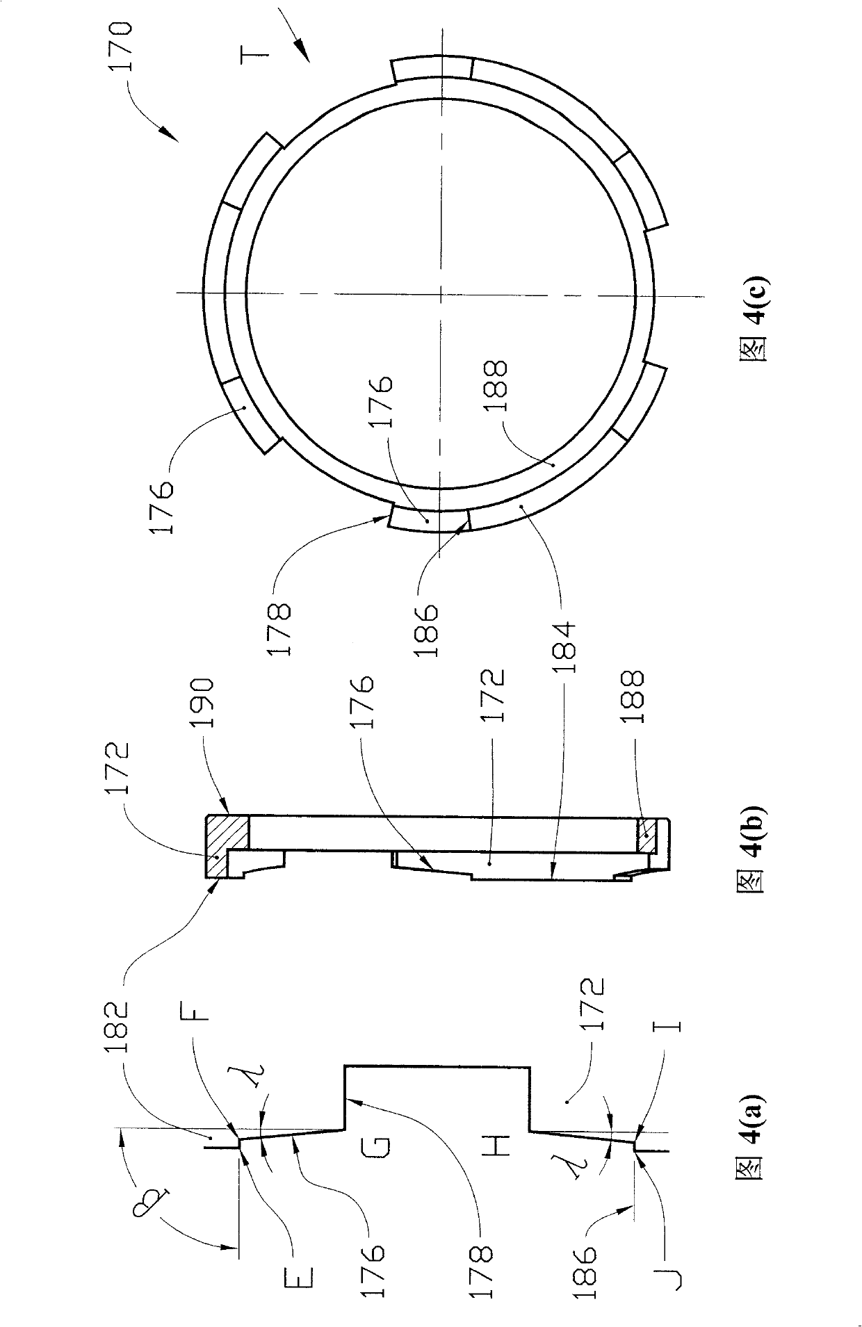
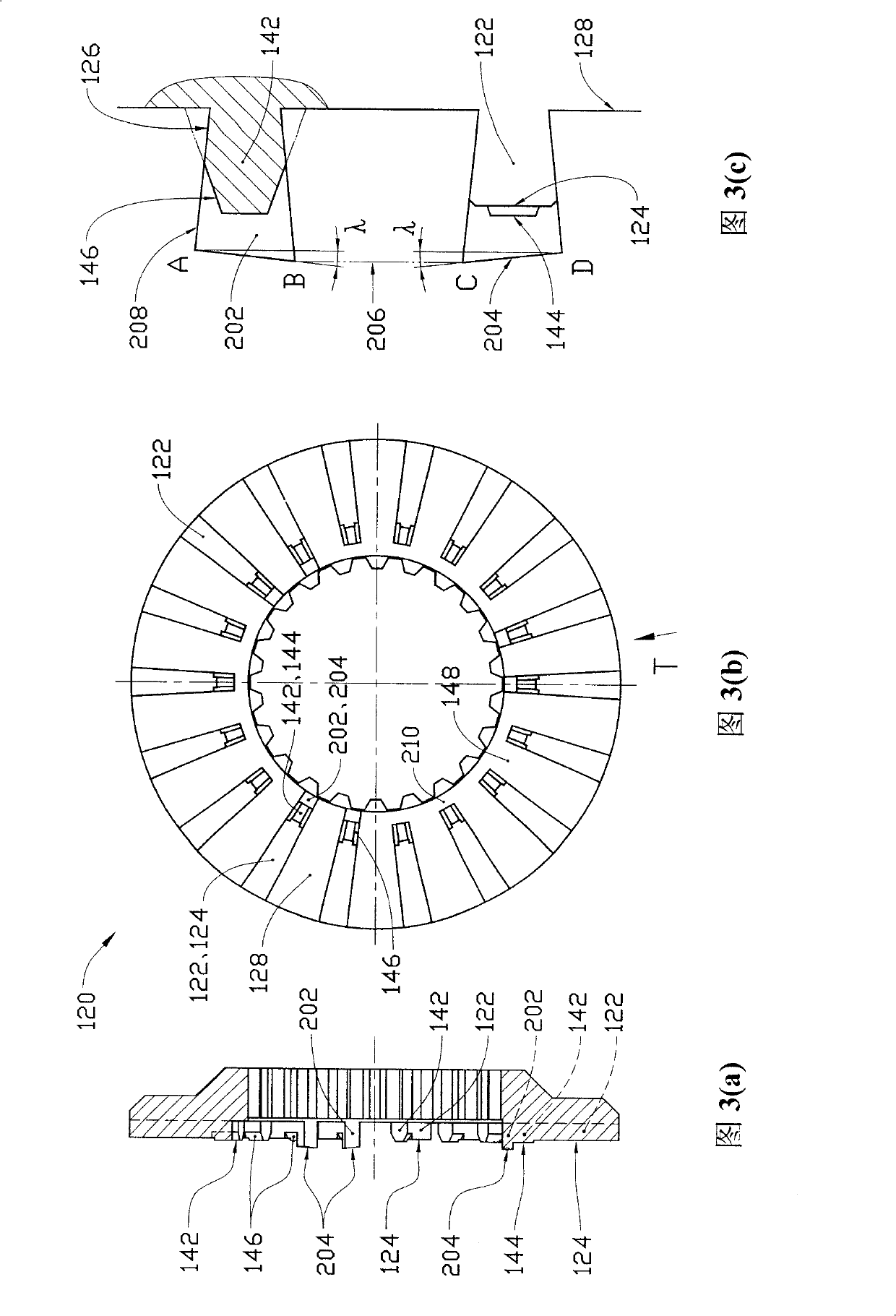
[0064] figure 2 ~ Figure 5 shows the first embodiment of the present invention, that is, the preferred embodiment of the present invention. The central ring 150 is embedded in the inner hole of the driving ring 110 and is axially fixed by the snap ring 56. The two driven rings 120 are installed at both ends of the driving ring 110. The mating end faces of the four rings face each other to form two force transmission inserts. One mechanism and two separate fitting mechanisms. The two springs 54 respectively press the driven ring 120 from both ends to ensure continuous presence of the fitting pressure, and the outer ends of the two springs 54 are supported by the two ...
PUM
 Abstract
Description
Claims
Application Information