Machining line

A processing line and processing station technology, applied in the direction of metal processing, metal processing equipment, manufacturing tools, etc., can solve the problem of frequent deflection of the position, achieve the effect of reducing energy consumption, reducing manufacturing costs, and eliminating power peaks

Inactive Publication Date: 2008-03-26
GROB WERKE & K G
View PDF0 Cites 9 Cited by
  • Summary
  • Abstract
  • Description
  • Claims
  • Application Information

AI Technical Summary

Problems solved by technology

Therefore, the smallest distance between the individual processing stations is determined according to the largest individual processing station and there is a risk of frequent deflection of the positions

Method used


Image

  • Machining line
  • Machining line
  • Machining line

Examples


Embodiment Construction

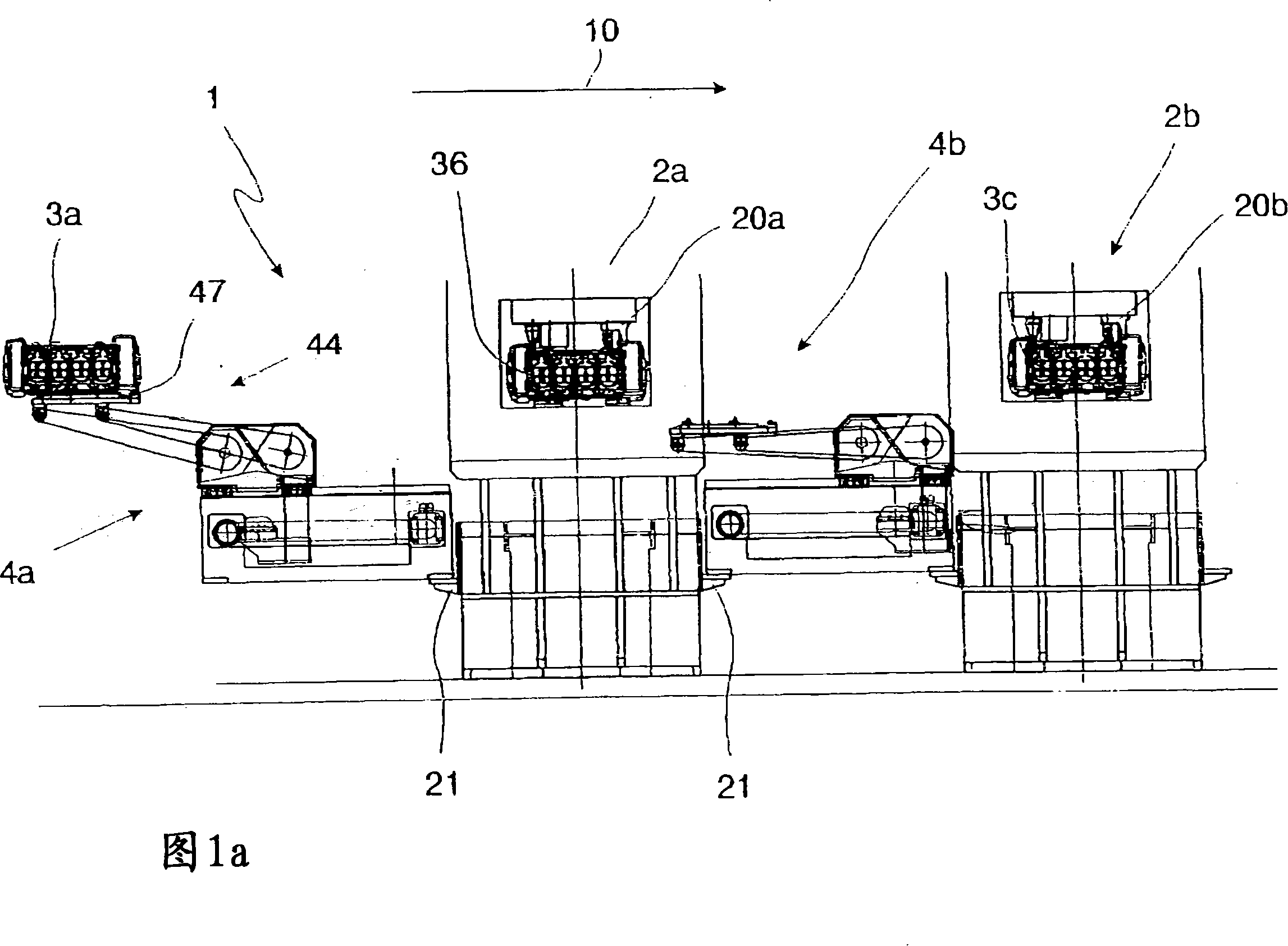
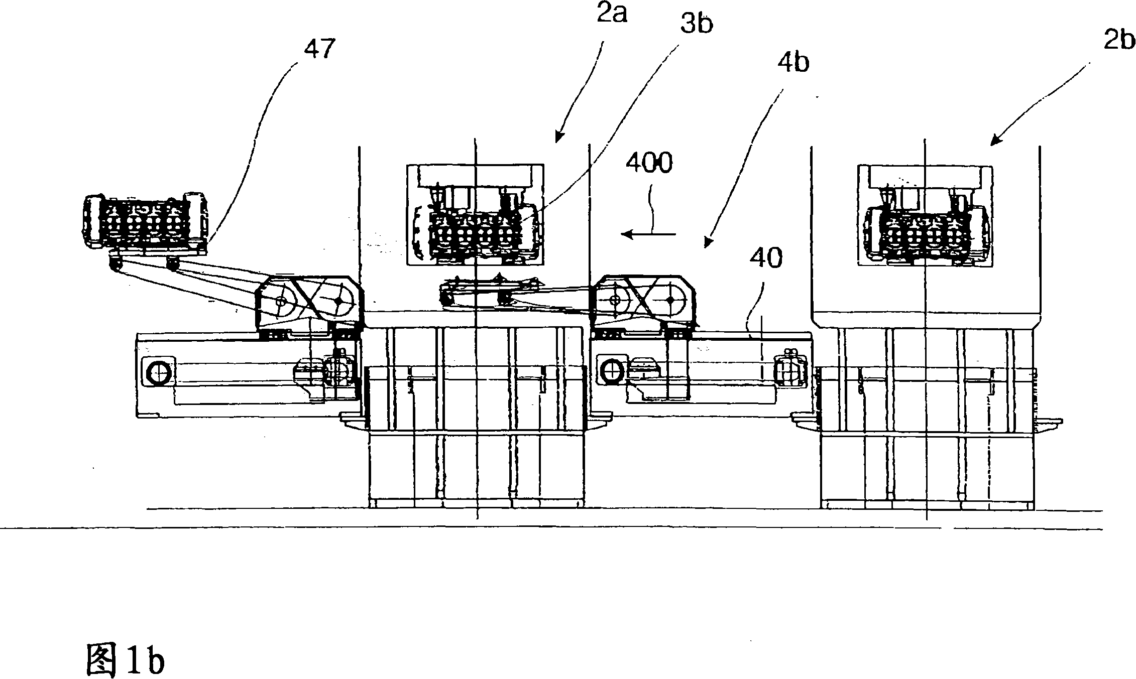
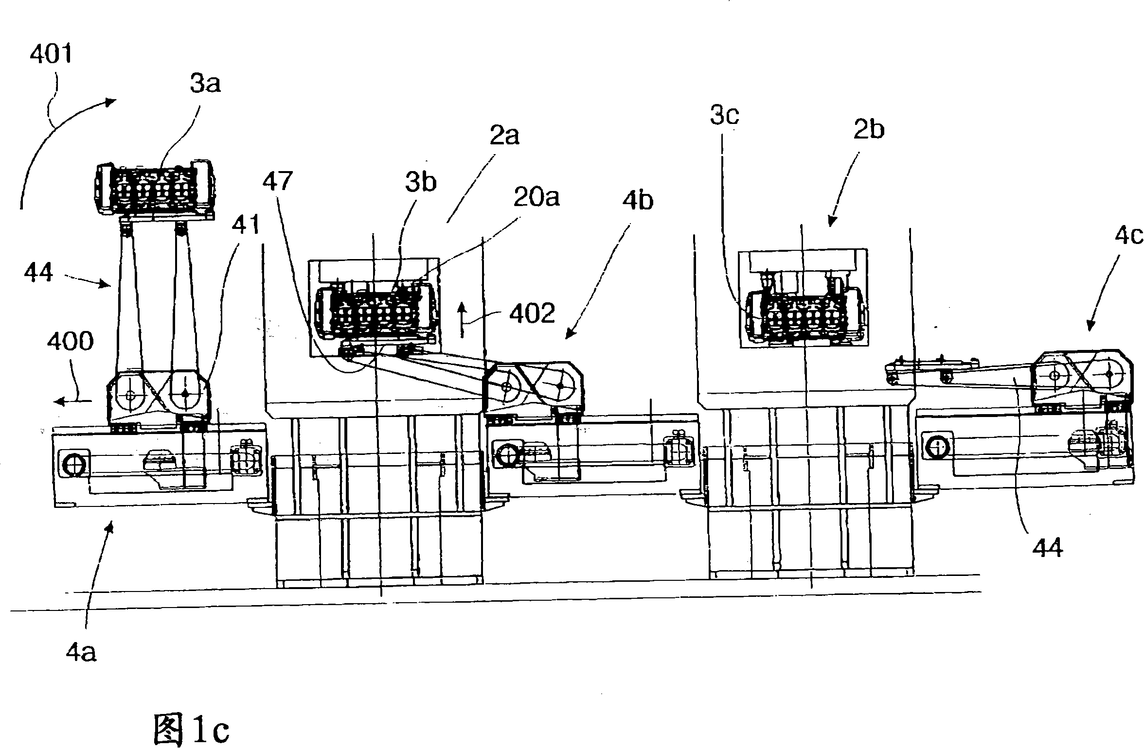
[0051] A simplified construction of a processing line 1 according to the invention is shown in FIG. 1a. The processing line 1 here comprises a plurality of processing stations 2a, 2b arranged along the direction of movement 10 of the workpieces 3a, 3b, 3c. Between the individual processing stations 2a, 2b, etc., respectively, conveying devices 4a, 4b are arranged which are driven and operate independently of one another. The transport devices 4a, 4b are supported on carriages 21 on the processing stations 2a, 2b.

[0052] The direction of movement 10 runs from left to right on the paper. As a result, the workpiece 3 a delivered by the first transport device 4 a is loaded next into the processing station 2 a. This is of course only possible when the workpieces 3b located therein are transported out of the first processing station 2a by means of the second transport device 4b. This is also only possible after the workpiece 3b has left the first processing station 2a at the en...


PUM


Abstract

The invention refers to a machining line, in particular a transfer line or assembly line, comprising a multitude of machining stations arranged one after the other in the direction of machining, and the machining station serves for machining work pieces, wherein at least one machining station is designed as special station. The invention is characterized by the fact that between two adjoining machining stations one conveying device each is provided.

Description

technical field [0001] The invention relates to a processing line, in particular a transfer line or an assembly line, comprising a plurality of processing stations which are arranged one behind the other in the processing direction and which are used to process workpieces, wherein at least one processing station is designed as a special machine. Background technique [0002] As already mentioned above, the processing lines mentioned at the outset are sufficiently known, for example, as transfer automation lines from the prior art. [0003] The characteristic of the transmission automatic line is that the arranged workpieces are sequentially processed by the processing stations constituted as special machine tools and realize the transportation or transmission of each workpiece between each processing station for all workpieces at the same time through a transfer rod or a transfer beam. However, this solution described in the prior art is disadvantageous with regard to energy...

Claims


Application Information

Patent Timeline
Patent Type & Authority Applications(China)
IPC IPC(8): B23Q41/02B23Q7/14
CPCB23P21/004B23Q41/02
Inventor 布克哈特·格罗布
Owner GROB WERKE & K G
Why Eureka
Try Eureka