Check patentability & draft patents in minutes with Patsnap Eureka AI!

Cooling system for a combustion grate in an incineration plant

A technology for cooling fluid, circulating system

Inactive Publication Date: 2012-07-04
BABCOCK & WILCOX VOLUND AS
View PDF1 Cites 0 Cited by
  • Summary
  • Abstract
  • Description
  • Claims
  • Application Information

AI Technical Summary

Problems solved by technology

Such a cooling fluid circulation system is known for example in EP0804706, however, no specific mention is made of flexible pipes

Method used


Image

  • Cooling system for a combustion grate in an incineration plant
  • Cooling system for a combustion grate in an incineration plant
  • Cooling system for a combustion grate in an incineration plant

Examples


Embodiment Construction

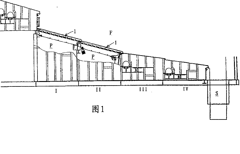
[0010] like figure 1 The waste heat incineration plant shown comprises several grate sections I-IV, each grate section comprising a grate beam 1 stepped downwards and a stationary grate beam in transverse direction, downwards The walking grate beams 1 extend in the direction of movement of the fuel over the top of the grate section and are arranged to move alternately. Thus, each grate section comprises a number of grate beams 1 arranged above the primary air chamber P in order to guide the primary air through the primary air openings in the grate.

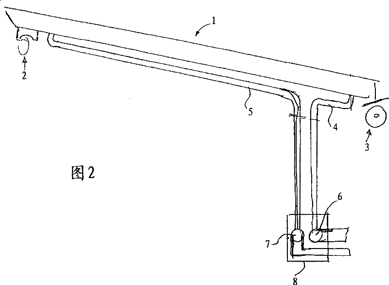
[0011] like figure 2 As shown, the movable grate beam 1 is provided with a moving mechanism 2 at one end and a supporting roller 3 at the opposite end, whereby the movable grate beam 1 can move in the longitudinal direction. The grate beam 1 is provided with cooling fluid channels (not shown in detail) which are supplied with cooling fluid through rigid tubes 4 which leave the grate beam through rigid tubes 5 . The pipelines 4...


PUM


Abstract

In a cooling fluid circulation system for an incineration or combustion grate in an incineration or combustion plant, the grate comprises a number of grate beams, at least some of which are movable for providing a movement of the fuel on top of said grate, primary air being blown through the grate from a primary air chamber below the grate Connections for circulating cooling fluid through said grate beams are positioned at the bottom side of said grate beams, inside said primary air chamber, and connected to rigid tubing, possible headers and flexible tubing, preferably in the form of bellow tubes, for providing a connection between moving tubing and stationary tubing in the cooling fluid circulation system. The flexible tubing is positioned outside the primary air chamber and the iead-infor the moving, rigid tubing through the wall of said primary air chamber is provided with a flexible bellow in order to avoid leakage of primary air along the tube. Hereby the flexible tubing is notsubjected to the grate screenings falling down from the grate and the high temperatures thereof.

Description

technical field [0001] The invention relates to a cooling fluid circulation system as stated in the preamble of claim 1 . Background technique [0002] In such cooling fluid circulation systems, it is known to arrange the grate beams movable so as to provide movement of the fuel over said grate top, and to blow the primary air through the grate from the primary air cavity below the grate . The connections for circulating the cooling fluid through the grate beams are usually located on the underside of the grate beams so as not to interfere with the movement of the fuel over the top of said grate. To allow the movable grate beam to move, flexible tubing is usually placed inside the main air chamber below the grate before the rigid tubing exits the main air chamber, thereby establishing a gap between the pipe and the side walls of the main air chamber. Fixed connection. Such a cooling fluid circulation system is known, for example, from EP0804706, however, no specific menti...

Claims


Application Information

Patent Timeline
Patent Type & Authority Patents(China)
IPC IPC(8): F23H3/02F23H7/08
CPCF23H7/08F23H3/02F23H2900/03021
Inventor 约翰·K·奥尔森
Owner BABCOCK & WILCOX VOLUND AS
Features
  • R&D
  • Intellectual Property
  • Life Sciences
  • Materials
  • Tech Scout
  • Unparalleled Data Quality
  • Higher Quality Content
  • 60% Fewer Hallucinations
Learn More