Nozzle for minisize gas-turbine combustor

A micro gas turbine and combustor technology, which is applied in the direction of combustors, continuous combustion chambers, burners, etc., can solve the problems of large changes, nozzle burnout, nozzle clogging, etc., to strengthen mutual shearing and reduce nozzle burnout , the effect of increasing the relative speed

Active Publication Date: 2010-12-08
江苏中国科学院能源动力研究中心 +1
View PDF8 Cites 2 Cited by
  • Summary
  • Abstract
  • Description
  • Claims
  • Application Information

AI Technical Summary

Problems solved by technology

[0004] 1. Since the atomization quality of the centrifugal atomizing nozzle with a single oil circuit varies greatly with the inlet oil pressure (fuel flow), it cannot meet the atomization performance of the micro gas turbine unit at the start-up, rated working conditions and variable working conditions at the same time
[0005] 2. In order to achieve good atomization performance, the imported oil pressure required by the centrifugal nozzle is high, which will bring hidden dangers to the safety and stability of the unit, and also increase the manufacturing and operating costs of the entire unit pipeline
[0006] 3. Since the front end of the centrifugal atomizing nozzle is in the high temperature zone of the combustion chamber, there is no special cooling technology, which may easily cause the nozzle to burn out
At the same time, the fuel may coke, thereby clogging the nozzles
[0007] 4. Due to the high concentration of oil mist at the front end of the centrifugal atomizing nozzle, the oxygen content is relatively insufficient, resulting in insufficient fuel combustion and easy to produce exhaust smoke and other phenomena

Method used


Image

  • Nozzle for minisize gas-turbine combustor
  • Nozzle for minisize gas-turbine combustor
  • Nozzle for minisize gas-turbine combustor

Examples


Embodiment Construction

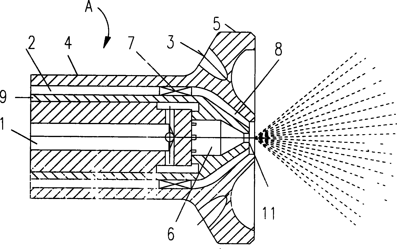
[0030] Figure 1 to Figure 4 It is a specific embodiment of the present invention.

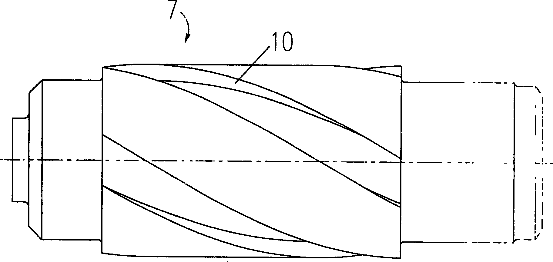
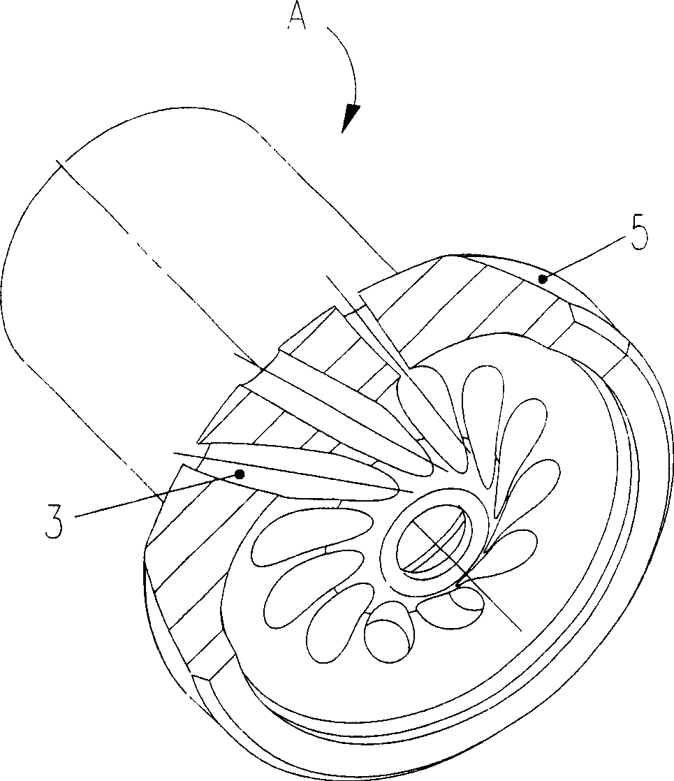
[0031] refer to figure 1 As shown, a micro gas turbine combustor nozzle A is a small-sized nozzle for a 100kW class micro gas turbine combustor. The wind injection channel 3 at the root of the device is composed of three parts. The diameter of the outer wall surface 4 of the nozzle A is not greater than 15 mm, and the diameter of the outer wall of the root 5 of the conical burner is not greater than 25 mm. On the premise of not increasing the manufacturing cost of nozzle A and adopting conventional processing methods, the efficient atomization of fuel can be achieved in such a small-scale space through optimized design. Among them, the oil circuit 1 is provided with a built-in centrifugal atomization device 6, the annular air circuit 2 for supplying atomized air is provided with an axial swirler 7, and an annular constriction 8 is provided before the atomized air is sprayed out. The oil de...


PUM


Abstract

The invention discloses a nozzle of a combustion chamber of a miniature gas turbine, relates to the gas turbine technology, and in particular to a small size fluid fuel nozzle used in a combustion chamber of a 100 kW level miniature gas turbine. The nozzle consists of three parts which are a fuel oil passage, a fuel air passage and an air channel at the root of a burner, comprehensively utilizes the advantages of pneumatic nebulization and pressure atomization, and is a combined type high performance pneumatic atomizing nozzle. The nozzle of the invention has the characteristics that: the nozzle adopts a conventional processing method to realize excellent atomization of the fuel in small scale space, so as to meet the requirement for the quality of fuel atomization under a quite wide burden of the combustion chamber of the miniature gas turbine; the nozzle can avoid burnout and overcomes the defect of nozzle blockage caused by high temperature coking of the fuel; meanwhile, the nozzlecan make the fuel in the combustion chamber to be combusted more fully and reduce discharge of pollutants such as smoke black and so on.

Description

technical field [0001] The invention relates to the technical field of gas turbines, and relates to a small-scale liquid fuel atomizing nozzle specially used in a combustion chamber of a 100kW micro gas turbine. Background technique [0002] Micro gas turbine is one of the main driving forces for distributed power generation and distributed energy supply. Its power is generally below hundreds of kilowatts. It generally adopts heat recovery cycle, and the power generation efficiency can reach 30% or higher. It has compact structure, small size, and high efficiency. high and high reliability. The combustor is one of the main components of a micro gas turbine. [0003] The fuel atomizing nozzle is one of the important parts of the combustion chamber, and its performance is directly related to the performance and life of the entire combustion chamber. In order to ensure the normal operation of the combustion chamber, the start-up of the unit and the performance of variable wor...

Claims


Application Information

Patent Timeline
Patent Type & Authority Patents(China)
IPC IPC(8): F23D11/38F23R3/38
Inventor 孔文俊汪凤山王宝瑞时晓军冯占祥劳世奇赵晓路
Owner 江苏中国科学院能源动力研究中心
Why Eureka
Try Eureka