Electric control inclined shaft plunger type hydraulic transformer

A technology of hydraulic transformer and inclined shaft column is applied in the field of hydraulic transformer, which can solve the problems of inconvenient operation and difficult to guarantee accuracy, and achieve the effects of convenient operation, simplified design and simplified structure form.

Inactive Publication Date: 2009-01-28
HARBIN INST OF TECH
View PDF0 Cites 15 Cited by
  • Summary
  • Abstract
  • Description
  • Claims
  • Application Information

AI Technical Summary

Problems solved by technology

[0003] The purpose of the present invention is to provide an electronically controlled inclined-axis plunger type hydraulic transformer to solve the pr

Method used


Image

  • Electric control inclined shaft plunger type hydraulic transformer
  • Electric control inclined shaft plunger type hydraulic transformer
  • Electric control inclined shaft plunger type hydraulic transformer

Examples


specific Embodiment approach 1

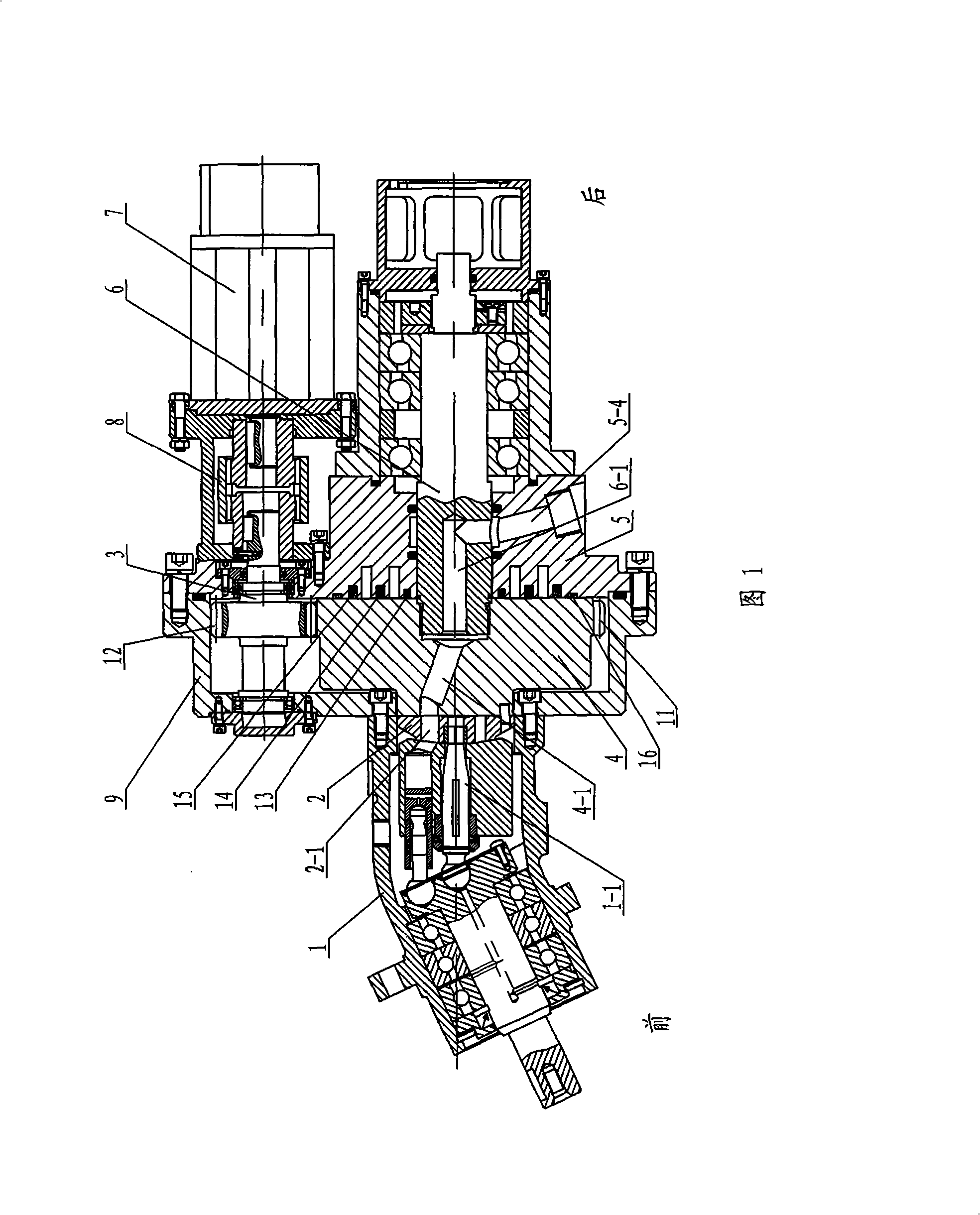
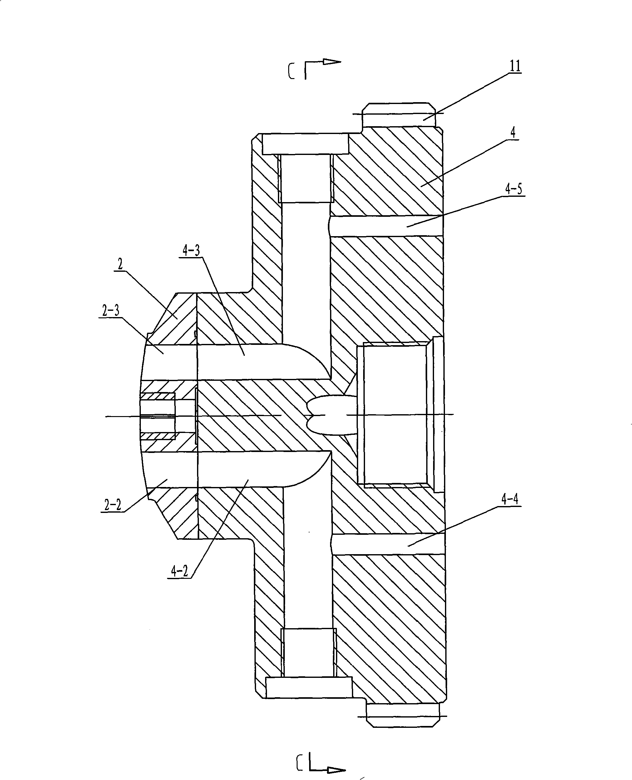
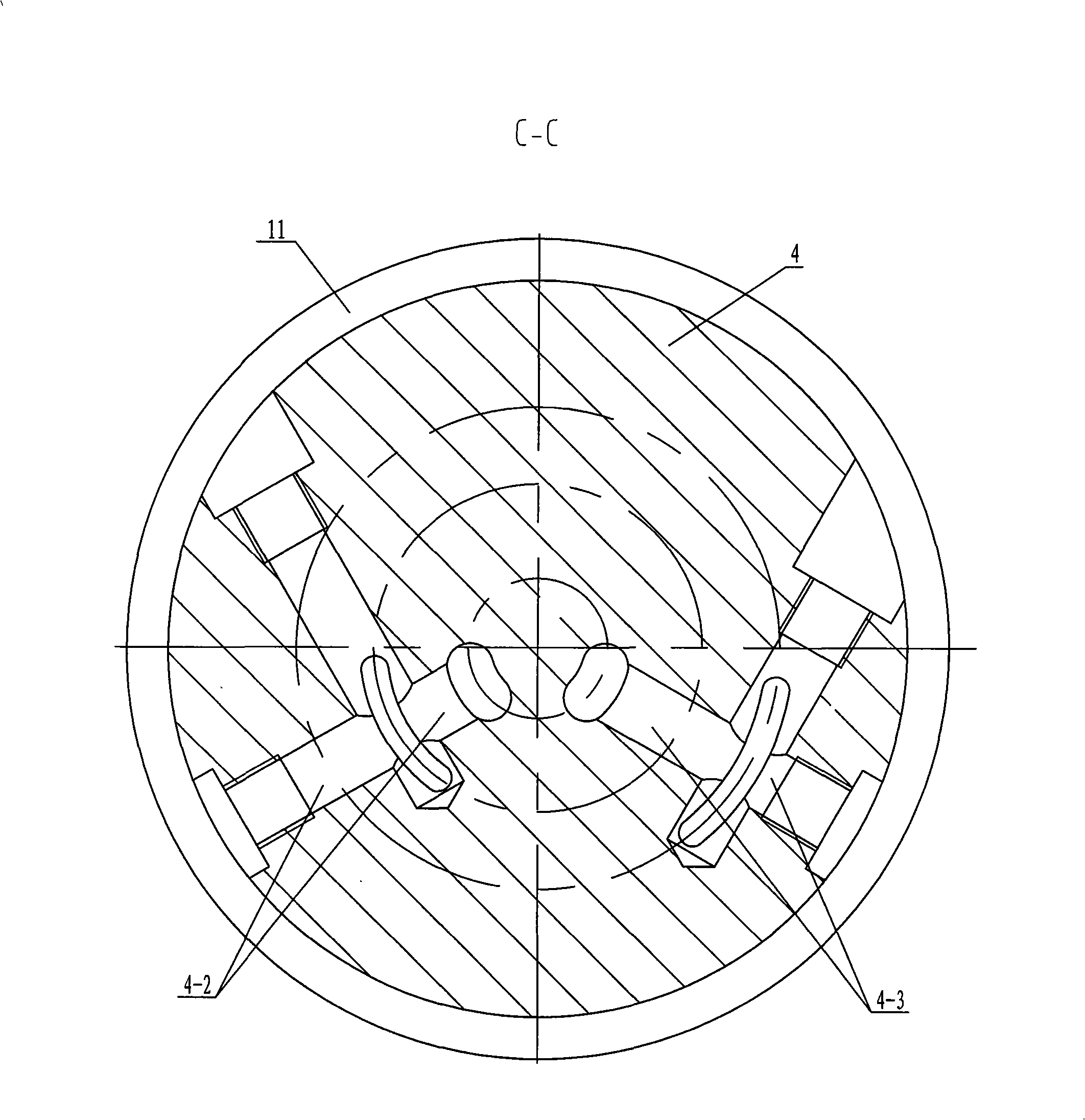
[0007] Specific embodiment one: in conjunction with Fig. 1 and figure 2 Describe this embodiment. This embodiment includes a plunger pump 1, a flow distribution plate 2, a gear shaft 3, a rear end cover 5, a flow distribution plate main shaft 6, a coupling 8 and a housing 9. The plunger pump 1 is fixed on the housing 9 One side of the distribution plate 2 is connected with the central rod 1-1 in the plunger pump 1, and the same circle on the distribution plate 2 is provided with a first distribution hole 2-1 and a second distribution hole 2-2 of the same shape. and the third distribution hole 2-3, the hydraulic transformer also includes a transition plate 4 and a servo motor 7, the front end of the transition plate 4 is arranged at the bottom of the housing 9 and connected with the flow distribution plate 2, the rear end of the transition plate 4 is connected to the The distribution plate main shaft 6 is connected, the rear end cover 5 is arranged on the distribution plate mai...

specific Embodiment approach 2

[0008] Specific embodiment two: in conjunction with Fig. 1 and figure 2 The present embodiment will be described. In this embodiment, the transition plate 4 and the driven gear 11 are integrally formed.

specific Embodiment approach 3

[0009] Specific Embodiment Three: This embodiment is described with reference to FIG. 1 . The gear shaft 3 and the driving gear 12 of this embodiment are integrated.


PUM


Abstract

The invention relates to a hydraulic transformer, in particular to an electrically controlled clino-axis piston hydraulic transformer. The hydraulic transformer of the invention aims at solving the problems that the current hydraulic transformer is mainly controlled by hands and is inconvenient for operation and difficult for ensuring precision. The front end of a transitional plate (4) of the invention is arranged in the lower part of a shell body (9) and connected with a port plate (2); the rear end of the transitional plate (4) is connected with a main shaft (6) of the port plate; a rear end cover (5) is arranged on the main shaft (6) of the port plate and fixedly connected with the shell body (9); the front end surface of the rear end cover (5) mutually contacts the rear end surface of the transitional plate (4); a driven gear (11) on the transitional plate (4) is meshed with a driving gear (12) on a gear shaft (3); the gear shaft (3) is connected with the outputting end of an servo motor (7) by a coupler (8). The servo motor is adopted in the invention to control the rotating angle of the driven gear by the gear shaft; servo control is introduced, thus not only having convenient operation, but also being capable of realizing precise control and improving the controlling performance of a system.

Description

technical field [0001] The invention relates to a hydraulic transformer. Background technique [0002] Existing hydraulic transformers are mainly controlled manually. The principle is that the manual control lever is coaxial with the driving gear, and the driven gear is controlled by the manual control lever, that is, the rotation angle of the hydraulic transformer distribution plate is controlled to realize voltage transformation. The disadvantage of manual control is that the operation is inconvenient and the accuracy is difficult to guarantee. Contents of the invention [0003] The purpose of the present invention is to provide an electronically controlled inclined-axis plunger type hydraulic transformer to solve the problems that the existing hydraulic transformer is mainly controlled manually, the operation is inconvenient, and the accuracy is difficult to guarantee. [0004] The invention includes a plunger pump, a flow distribution plate, a gear shaft, a rear end c...

Claims


Application Information

Patent Timeline
IPC IPC(8): F15B13/00F15B5/00
Inventor 姜继海卢红影
Owner HARBIN INST OF TECH
Why Eureka
Try Eureka