Radio communication device

A wireless communication device and antenna technology, applied in the transmission system, telephone structure, electrical components, etc., can solve problems such as multiple hardware spaces, and achieve the effect of reducing hardware space

Active Publication Date: 2012-04-04
HTC CORP
View PDF0 Cites 0 Cited by
  • Summary
  • Abstract
  • Description
  • Claims
  • Application Information

AI Technical Summary

Problems solved by technology

In other words, the traditional wireless communication device 100 must consume more hardware space to improve the transceiver capability of the antenna 140

Method used


Image

  • Radio communication device
  • Radio communication device
  • Radio communication device

Examples


Embodiment Construction

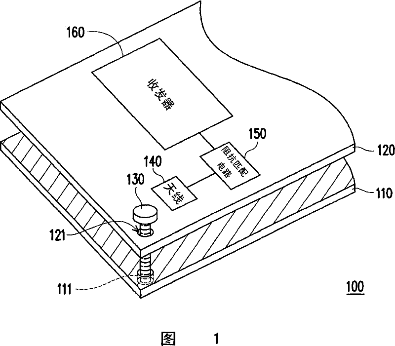
[0022] The main technical feature of the present invention is that in the wireless communication device of the present invention, the antenna used to receive or transmit electromagnetic signals also has the function of fixing the housing and the substrate. The wireless communication device of the present invention will be illustrated below, but it is not intended to limit the present invention. Those skilled in the art can slightly modify the following embodiments according to the spirit of the present invention, but they still belong to the scope of the present invention.

[0023] In addition, before describing the spirit of the present invention with the embodiments, the expandable wireless communication devices listed in the following embodiments are described here, which can be PDA mobile phones, smart phones, satellite navigators or personal digital assistants, etc. , is not limited here.

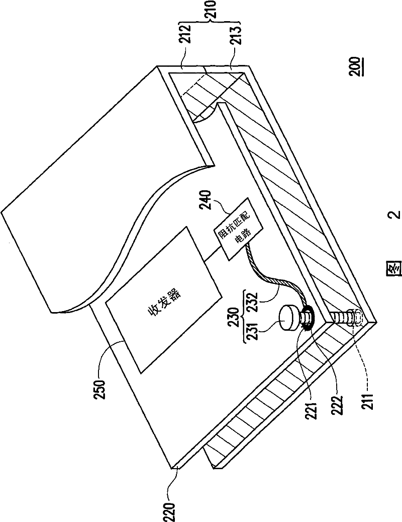
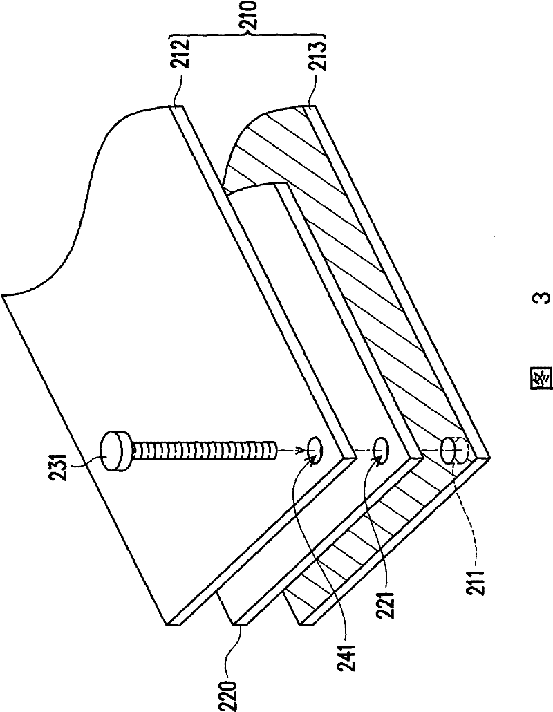
[0024] figure 2 It is a schematic structural diagram of a wireless communication...


PUM


Abstract

The invention discloses a wireless communication apparatus, comprising a shell, a base plate and an antenna, wherein, a first guide hole is arranged on the edge of the base plate, and the antenna includes a body part. Herein, the antenna utilizes the body part to receive or transmit an electromagnetism signal. On the other hand, the body part of the antenna can penetrate through the first guide hole and be locked in the shell, so the base plate can be fixed in the shell.

Description

technical field [0001] The present invention relates to a wireless communication device, and in particular to a wireless communication device using a fixed device to send and receive signals. Background technique [0002] At present, the communication methods of the general public have gradually entered the era of wireless communication, so the usage rate of wireless communication devices in various occasions is getting higher and higher, and it is becoming more and more diversified, such as mobile phones, smart phones, multimedia Players, personal digital assistants, satellite navigators, etc., various small wireless communication devices have been gradually developed, and have become electronic products that people must have in their daily lives. [0003] Generally speaking, the way for wireless communication devices to receive and process signals is to first receive the signal through the antenna, then transmit the signal received by the antenna to the circuit, and then s...

Claims


Application Information

Patent Timeline
Patent Type & Authority Patents(China)
IPC IPC(8): H04M1/02H04B1/38H04B1/3827
Inventor 洪崇庭
Owner HTC CORP
Why Eureka
Try Eureka