Alignment adjustment method of blocking component, controller and gate equipment

An adjustment method and a technology of blocking parts, which are applied in the direction of electric speed/acceleration control, etc., to achieve the effects of saving hardware costs, simple operation, and improving reliability

Active Publication Date: 2021-08-06
HANGZHOU HIKVISION DIGITAL TECH
View PDF14 Cites 0 Cited by
  • Summary
  • Abstract
  • Description
  • Claims
  • Application Information

AI Technical Summary

Problems solved by technology

[0008] The application provides an alignment adjustment method of blocking components to solve the alignment adjustment of blocking components in gate equipment using direct drive motors

Method used


Image

  • Alignment adjustment method of blocking component, controller and gate equipment
  • Alignment adjustment method of blocking component, controller and gate equipment
  • Alignment adjustment method of blocking component, controller and gate equipment

Examples


Embodiment Construction

[0057] In order to make the purpose, technical means and advantages of the present application, the present application will be further described below with reference to the accompanying drawings.

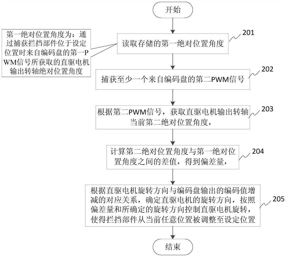
[0058] The present application is recorded by the first absolute position angle of the direct drive motor output rotating shaft when the shutter member is located in the set position, and then the second absolute position angle of the direct-drive motor output rotation axis is in the current arbitrary position. The difference between the absolute position angle, controls the direct drive motor rotation, so that the shuttle member is adjusted from the current any position to the set position, wherein the first absolute position angle, the second absolute position angle is attached to the direct drive motor output by capturing The PWM signal output from the shaft is determined.

[0059] See figure 2 Distance figure 2 A flow diagram of an alignment adjustment method of an intercepting mem...


PUM


Abstract

The invention discloses an alignment adjustment method for a blocking component. The method comprises steps of carrying out alignment adjustment of the blocking component at a drive controller side used for controlling a direct drive motor; according to a deviation value between a first absolute position angle of an output rotating shaft of the direct-drive motor when the blocking component is located at the set position and a second absolute position angle of the output rotating shaft of the direct-drive motor when the blocking component is located at any position, the direct-drive motor is controlled to rotate, and the blocking component is adjusted to the set position from the current any position; the first absolute position angle and the second absolute position angle are determined by capturing pulse width modulation (PWM) signals outputted by a coding disc installed on an output rotating shaft of the direct drive motor. The method is advantaged in that position detection devices such as a travel switch and a detection rod do not need to be additionally installed, hardware cost and the mechanism size space are saved, miniaturization and refinement of a machine core structure can be conveniently achieved through direct drive, and reliability is improved due to the fact that connecting cables of the in-place switch plate are reduced.

Description

Technical field [0001] The present application relates to the field of entrance and exit control, and in particular, to an alignment adjustment method of a break member. Background technique [0002] The gate of the entrance and exit is a machine-coupled control component, which is mounted to the accessible entrance, in the fuselage and the body, or the body and other building facilities, and drive the barrier component with the driver. The object is executed in an entrance control system in which you are in order in the specified direction. The shutter device can include a type of pendulum, three stick brakes. [0003] During the production and installation and commissioning of the gate device, the barrier component is inevitable as a mechanical structure. As an example, figure 1 A top view of a use principle of a shutter device, which lists the channels formed between the body and the shutter gate on the passage, and lists several gate alignment. Among them, the two gates in th...

Claims


Application Information

Patent Timeline
Patent Type & Authority Applications(China)
IPC IPC(8): G05D13/62
CPCG05D13/62
Inventor 李长水王升国赵先林
Owner HANGZHOU HIKVISION DIGITAL TECH
Why Eureka
Try Eureka