Fan with magnetic blades

a technology of blades and fans, applied in the direction of magnetic circuit rotating parts, magnet circuit shape/form/construction, piston pumps, etc., can solve the problems of reducing the efficiency of the fan unit, increasing manufacturing costs and power consumption,

Inactive Publication Date: 2001-02-27
AIR CONCEPTS
View PDF25 Cites 105 Cited by
  • Summary
  • Abstract
  • Description
  • Claims
  • Application Information

AI Technical Summary

Benefits of technology

Various important advantages result from a fan design according to the principles of the present invention, such as reduction in manufacturing costs, increased impeller airflow area, increased airflow per unit power consumed, reduced losses, enhanced miniaturization of fan dimensions while achieving low power consumption and high airflow specifications. This last benefit is important for small fans used, for example, in electronic equipment such as personal computers, fan trays, and a vast variety of electronic instrumentation apparatus.

Problems solved by technology

The fan units disclosed in both of these prior patents and, indeed, in the known prior art suffer from the disadvantage of requiring large mass ring member that encircles the distill edges of the blades in order to establish the N-S radially oriented magnetic segments that cooperate with the stator electromagnetic fields to generate torque and motion.
These members prevent miniaturization of the fan design, require a large mass ring member or expensive magnetic materials which increases manufacturing cost and power consumption during operation and generally lowers the efficiency of the fan unit.

Method used


Image

  • Fan with magnetic blades
  • Fan with magnetic blades
  • Fan with magnetic blades

Examples


embodiment 10

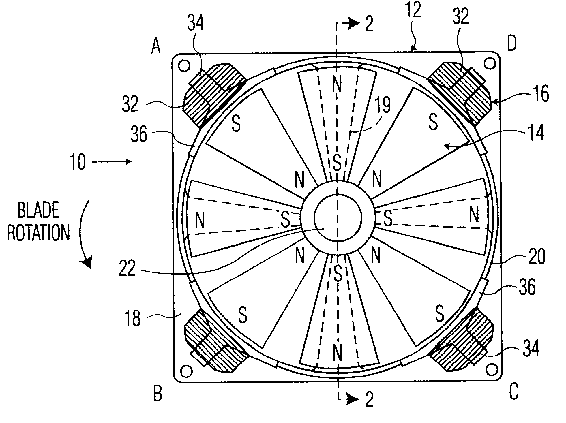
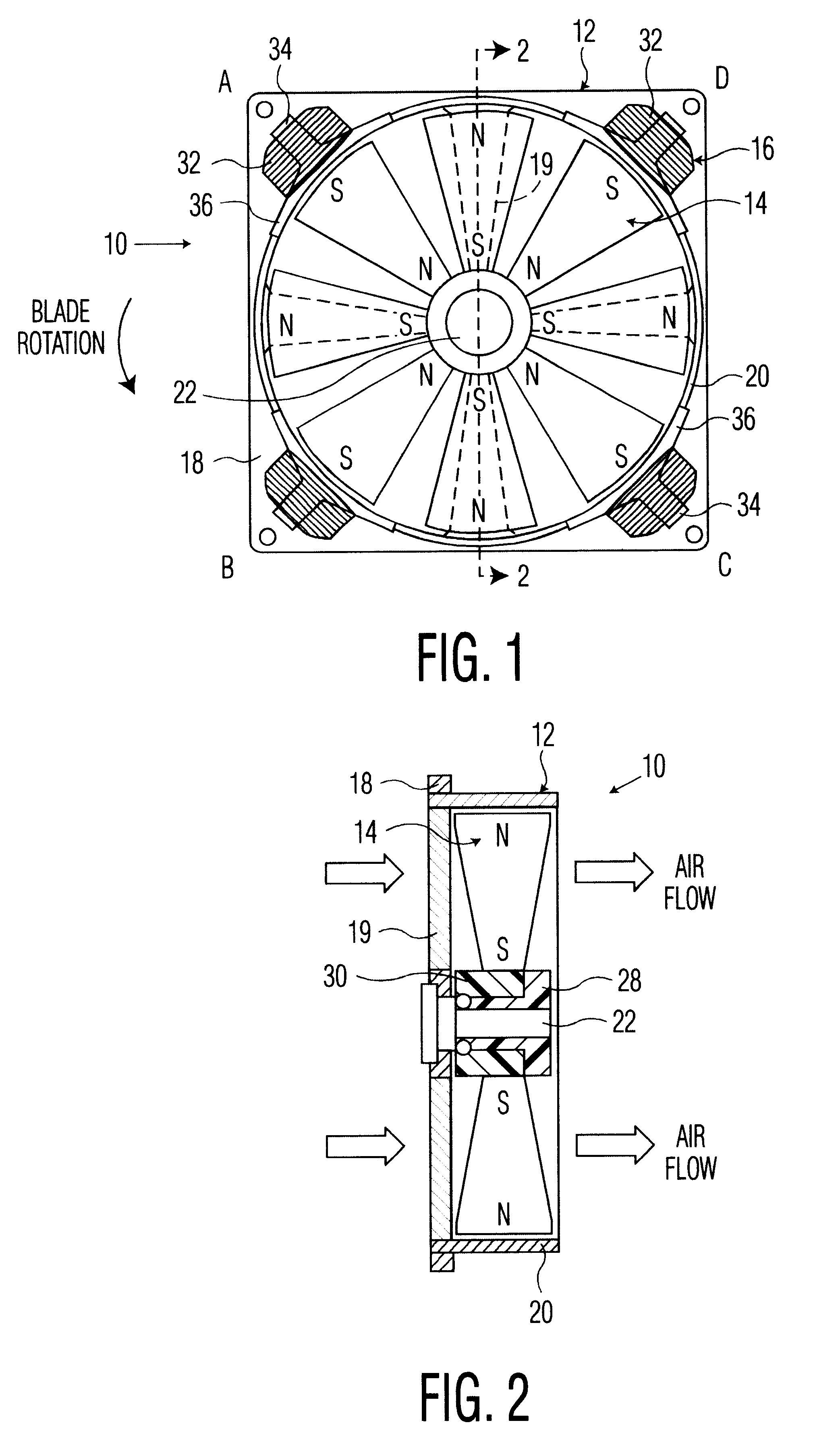
One fan embodiment 10 according to the principles of the present invention is shown in FIG. 1-4 and includes a housing 12, rotor impeller assembly 14 and stator coil assembly 16.

Housing 12 includes a plate or frame member 18 preferably supporting a cylindrical ring, cowling or shroud 20 that confines and directs the air flow indicated generally by the arrows in FIG. 2. Frame 18 includes struts 19 spaced sufficiently to enable at least maximum rated intake air to pass through in response to impeller operation described below. Frame 18 and struts 19 also mounts and supports the impeller axis or shaft 22.

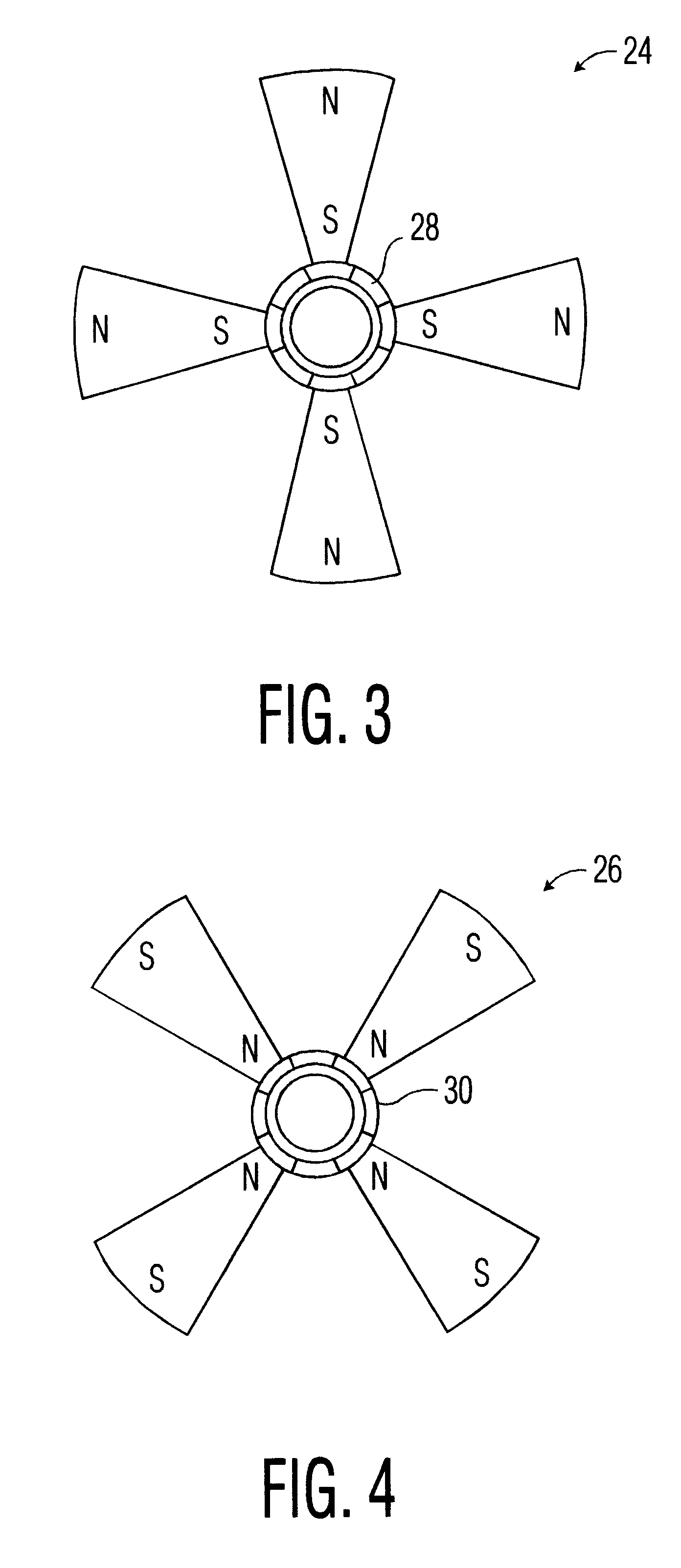
In this exemplary embodiment, the impeller assembly 14 includes two sub-impellers 24 and 26 each having four blades, each blade being formed of suitable material that can function as a permanent magnet with sufficient mechanical strength to function as described below. Examples include ferromagnetic impregnated plastics and ferrous materials (such as steel, iron, or ferrous alloys) tha...


PUM


Abstract

A DC driven fan with blades made of magnetized material and permanently magnetized in the radial direction and cooperating with a plurality of electromagnetic stator coils mounted external to the outer fan edges. Adjacent blades have alternate N-S, S-N radial magnetic orientations. In one embodiment, the blades are mounted in a non-ferrous hub and in an alternate embodiment they are mounted in a ferrous hub so that adjacent blades function like a U or V-shaped magnet. Blades can be made of magnetized ferrous, ferromagnetic, or magnetized plastic depending upon the application and blade strength specifications.

Description

Not ApplicableNot ApplicableREFERENCE TO A "MOCROFICHE APPENDIX"Not ApplicableThis invention relates to fans and more particularly to DC motor driven fans with stator electromagnets displaced radially beyond the periphery of the rotor.DESCRIPTION OF RELATED ARTThis type of fan is known, for example, by U.S. Pat. Nos. 4,553,075 and 4,459,087. The '075 patent includes an annular permanent magnet magnetized in segments about its circumference. Each segment is oppositely radially magnetized with respect to its adjacent segments. Fan blades are located within the annular magnet. A coil comprising two electrically independent bifilar wound windings, connected to be oppositely energized, and an electromagnet structure defining two pole pieces reside outside the permanent magnet annulus. A Hall effect device alternately energizes the separate coil windings in response to passage of the segments of the rotor magnet to alternately produce opposite magnetic fields in the pole pieces.The '087 p...

Claims


Application Information

Patent Timeline
Patent Type & Authority Patents(United States)
IPC IPC(8): F04D25/06F04D25/02H02K7/14
CPCF04D25/066H02K7/14F04D25/0606F04D29/281F04D29/30F04D29/327
Inventor LOPATINSKY, EDWARD
Owner AIR CONCEPTS
Why Eureka
Try Eureka