Hydraulic-mechanical integrated sand discharge apparatus

A mechanical and hydraulic technology, applied in the field of water conservancy and hydropower engineering, can solve the problems of low sand discharge efficiency, limited volume of sand discharge funnel, etc., and achieve good social and economic benefits, high sand discharge efficiency, and a wide range of applications.

A mechanical and hydraulic technology, applied in the field of water conservancy and hydropower engineering, can solve the problems of low sand discharge efficiency, limited volume of sand discharge funnel, etc., and achieve good social and economic benefits, high sand discharge efficiency, and a wide range of applications.

CN101372835AInactive Publication Date: 2009-02-25张金良

Image

  • Hydraulic-mechanical integrated sand discharge apparatus
  • Hydraulic-mechanical integrated sand discharge apparatus

Examples


Embodiment

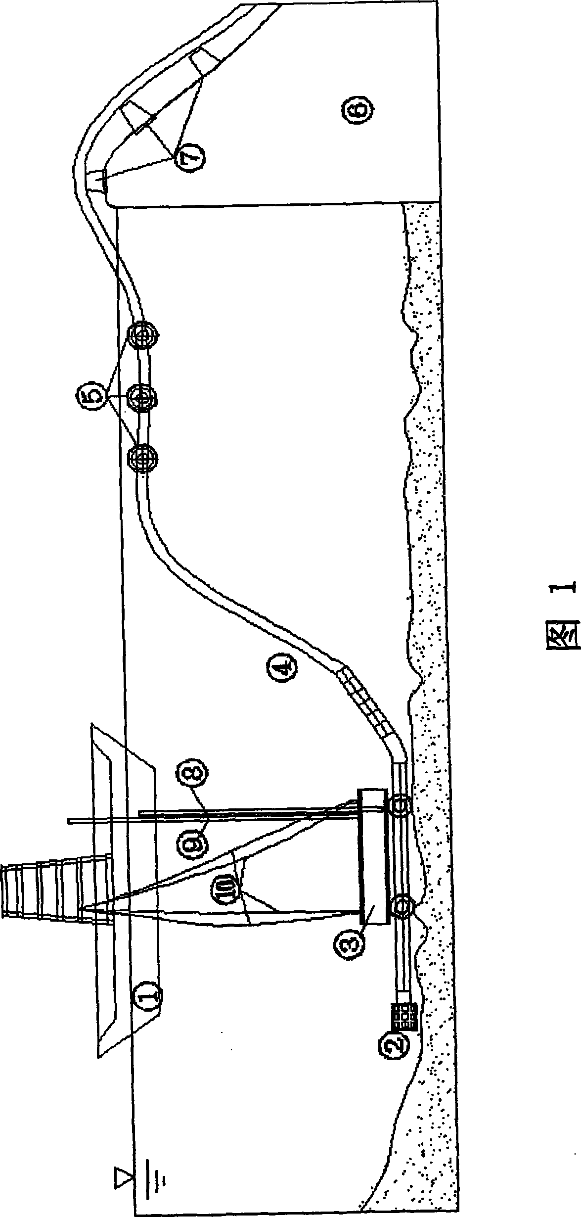
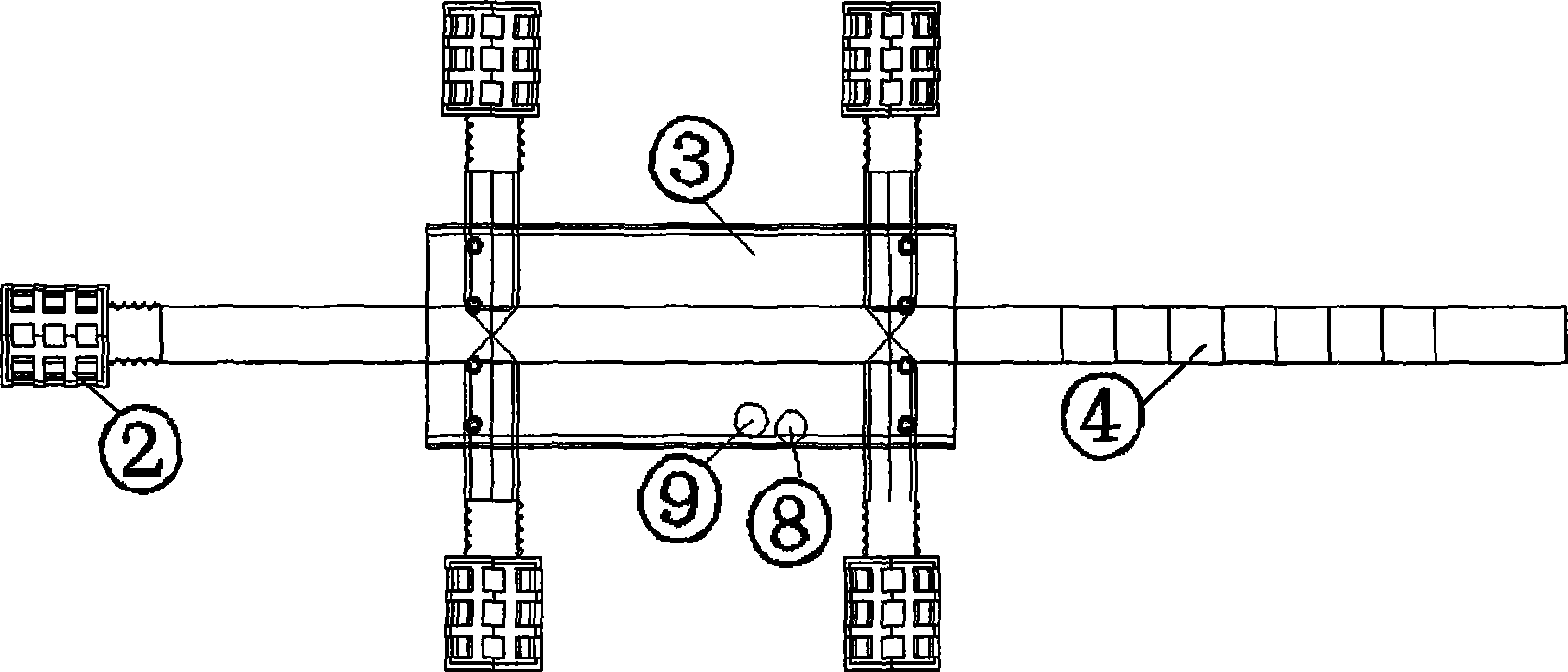
[0017] Example: See Figure 1 and figure 2 , in the figure, a sand suction device 2 is installed at the head end of the siphon type sand delivery pipe 4 of the hydraulic-mechanical integrated sand removal device, and the sand suction device 2 is fixed with a submersible box 3, and the submersible box 3 is connected to the water surface through a steel cable 10. The tugboat 1 is connected to facilitate movement, and the submersible tank 3 is provided with an air intake pipe 9 and a discharge pipe 8. The control valves of the air intake pipe 9 and the discharge pipe 8 are arranged on the tugboat 1, and the air intake pipe 9 is connected with the pressure gas source and the water source respectively. Conversion is communicated, is convenient to ventilate or pass water in the intake pipe 9. The tail end of the siphon sand delivery pipe 4 is fixed on the pier 7 provided on the dam body 6 . In order to increase the buoyancy of the tail end of the siphon sand delivery pipe 4, a buoy ...


PUM


Abstract

The invention discloses a hydraulic-mechanical integrated sand-flushing device, which comprises a siphoning type sandline; the head end of the siphoning type sandline is provided with a sand sucker while the tail end thereof is fixed on a rest pier arranged on a dam body; the sand sucker is fixed with a pontoon that is connected to a towing vessel on water surface through steel cables to facilitate movement. Further, the pontoon is provided with an air inlet pipe and a water drain pipe; control valves of the air inlet pipe and the water drain pipe are set on the towing vessel; the air inlet pipe is in switch communication with a pressure air source and a water source so that air or water is led into the air inlet pipe. The sand sucker has a plurality of sand sucking nozzles, the ends of which are all sealed; the side wall thereof is provided with a plurality of sand sucking holes. The invention utilizes a novel sand flushing concept for integrating hydraulic power and machinery to change traditional modes which use a mechanical dredging (sucking) and sand discharging method or hydraulic sand discharging method merely; the invention transports sands by mainly using natural force (hydraulic power), with reduced energy consumption, high sand transporting efficiency and good social and economic effects.

Description

1. Technical field: [0001] The invention relates to a sand discharge device, in particular to a hydraulic-mechanical integrated sand discharge device, which belongs to the technical equipment in the field of water conservancy and hydropower engineering. 2. Background technology: [0002] At present, there are two types of sand removal technologies used in reservoirs, rivers or waterways: one is mechanical sand dredging: dredgers are equipped with various suction devices. This sand removal method requires additional energy to transport the mud to the designated location. Large reservoir silt then will pay a considerable price to achieve the goal. The other is hydraulic sand transport: using the characteristics of sediment movement to transport the sediment to the sand discharge outlet and then discharged from the sand discharge hole. Although this sand discharge method uses hydraulic sand transport and does not require additional energy, it must Only by transporting the sedi...

Claims


Application Information

Patent Timeline
25 Feb 2009
Publication
CN101372835A
IPC
E02F5/28; E02F3/88
Inventors
张金良; 练继建