Bearing capper

A technology of capping machine and bearing, which is applied in the direction of bearing components, shafts and bearings, mechanical equipment, etc., and can solve problems such as capping

Inactive Publication Date: 2010-06-16
SHANGHAI UNITED BEARING
View PDF5 Cites 0 Cited by
  • Summary
  • Abstract
  • Description
  • Claims
  • Application Information

AI Technical Summary

Problems solved by technology

[0004] The purpose of the present invention is to solve the above-mentioned 26 railway bearing capping problems, and provide a bearing capping machine with an easily adjustable and positioned upper and lower mold supporting the 26 railway bearings

Method used


Image

  • Bearing capper
  • Bearing capper
  • Bearing capper

Examples


Embodiment Construction

[0010] The present invention will be further described in detail below in conjunction with the accompanying drawings and embodiments.

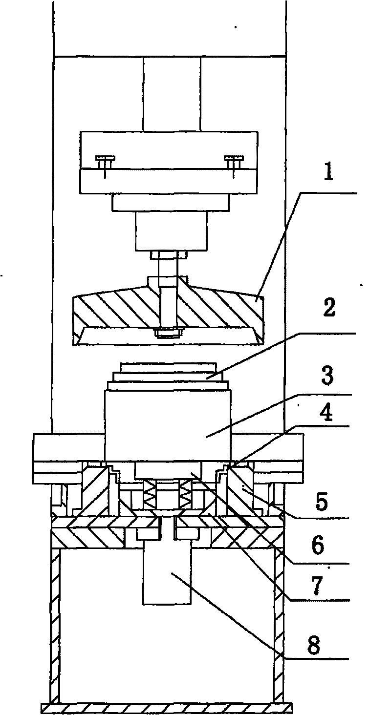
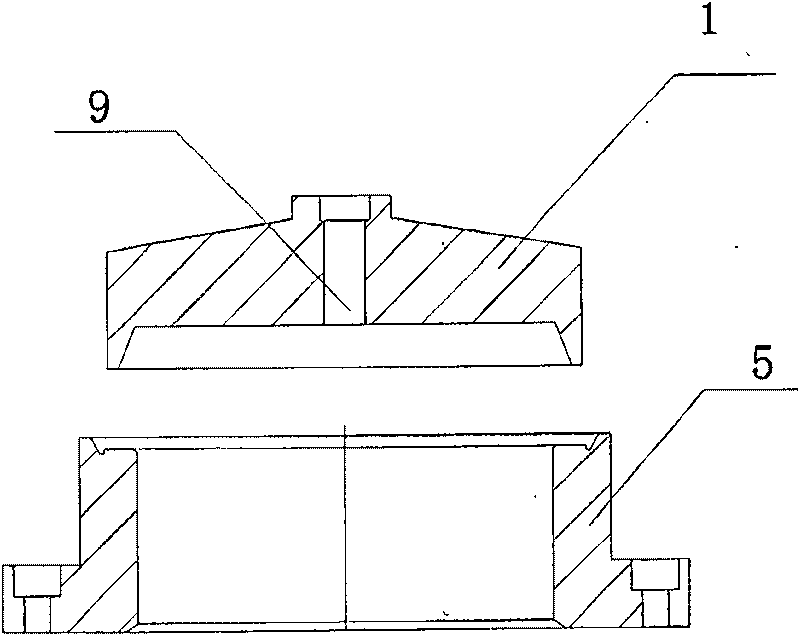
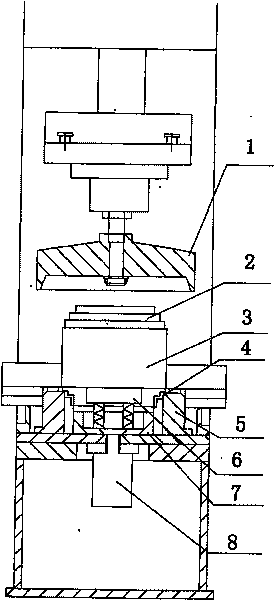
[0011] refer to figure 1 with 2 , a bearing capping machine, comprising a hydraulic press, a cylinder 8, an inner ring positioner 6, an upper die 1 and a lower die 5, the upper die 1 is connected to the screw of the hydraulic press 7, the lower die 5 is connected to the working surface of the hydraulic press, and the inner ring The locator 6 is located at the upper center of the lower mold 5, and the cylinder 8 is located below the lower mold. It can pass through the lower mold 5 and contact the inner ring locator 6 to eject the bearing workpiece. The lower mold 5 supports the outer ring of the bearing. , the inner ring locator 6 supports the inner ring of the bearing, and it is characterized in that the cross-sectional shape of the upper and lower molds matches the outer ring of the bearing, and the upper and lower molds are equipped with T-...


PUM


Abstract

The present invention relates to a bearing manufacture equipment, particularly relates to a bearing capping machine. The capping machine includes a hydrostatic press, an air cylinder, an inner lane locater, an upper mould and a lower mould, wherein the upper mould connects with the screw rod of the hydrostatic press; the lower mould connects with the working table of the hydrostatic press; the inner lane locater locates above the lower mould in central position of the lower mould; the air cylinder locates below the lower mould and can pass the lower mould to contact with the inner lane locaterand push-out the bearing work piece; the lower mould holds the outer lane of the bearing; the inner lane locater holds the inner lane of the bearing. The present invention characterized in that the shape and size of the intersecting surface of the upper and lower mould matches the outer lane of the bearing, and the upper and lower mould are provided with a T-shaped groove to adjust the central position of the upper and lower mould to align the upper and lower mould. By adopting above technical solution, the center locating of the upper and lower mould is accurate, operation is easy, hence capping speed and percent of pass are improved significantly.

Description

technical field [0001] The invention relates to bearing manufacturing equipment, in particular to a bearing capping machine. Background technique [0002] In the post-processing of bearing manufacturing, it is necessary to grease the bearing and even out the grease. In order to prevent dust, it is generally necessary to cover the outer ring of the bearing on the upper and lower ends of the bearing. [0003] Existing capping machines generally use a hydraulic system to pressurize, and cooperate with a suitable mold to press the sealing cap on the proper position of the bearing. Existing molds are generally divided into upper and lower molds, but due to the unreasonable design of the existing upper and lower molds, it is difficult to locate the upper and lower molds, and the positioning is easy to be inaccurate, resulting in unreasonable gland positions. However, there is no matching mold for the capping machine of 26 railway bearings. Contents of the invention [0004] T...

Claims


Application Information

Patent Timeline
Patent Type & Authority Patents(China)
IPC IPC(8): F16C43/04
Inventor 韦凯明
Owner SHANGHAI UNITED BEARING
Why Eureka
Try Eureka