Device for mixing light of side emitting leds

A technology of light-emitting devices and light-emitting diodes, which is applied to semiconductor devices of light-emitting elements, reflectors, components of lighting devices, etc., and can solve problems such as distance limitations

Inactive Publication Date: 2009-09-16
KONINK PHILIPS ELECTRONICS NV
View PDF0 Cites 1 Cited by
  • Summary
  • Abstract
  • Description
  • Claims
  • Application Information

AI Technical Summary

Problems solved by technology

However, the distance between the LEDs still poses a limitation, and when utilizing SE-LEDs, the distance between the SE-LEDs can be 1.5 times the distance between the LEDs and the diffuser while maintaining The essentially constant intensity level of the LED

Method used


Image

  • Device for mixing light of side emitting leds
  • Device for mixing light of side emitting leds
  • Device for mixing light of side emitting leds

Examples


Embodiment Construction

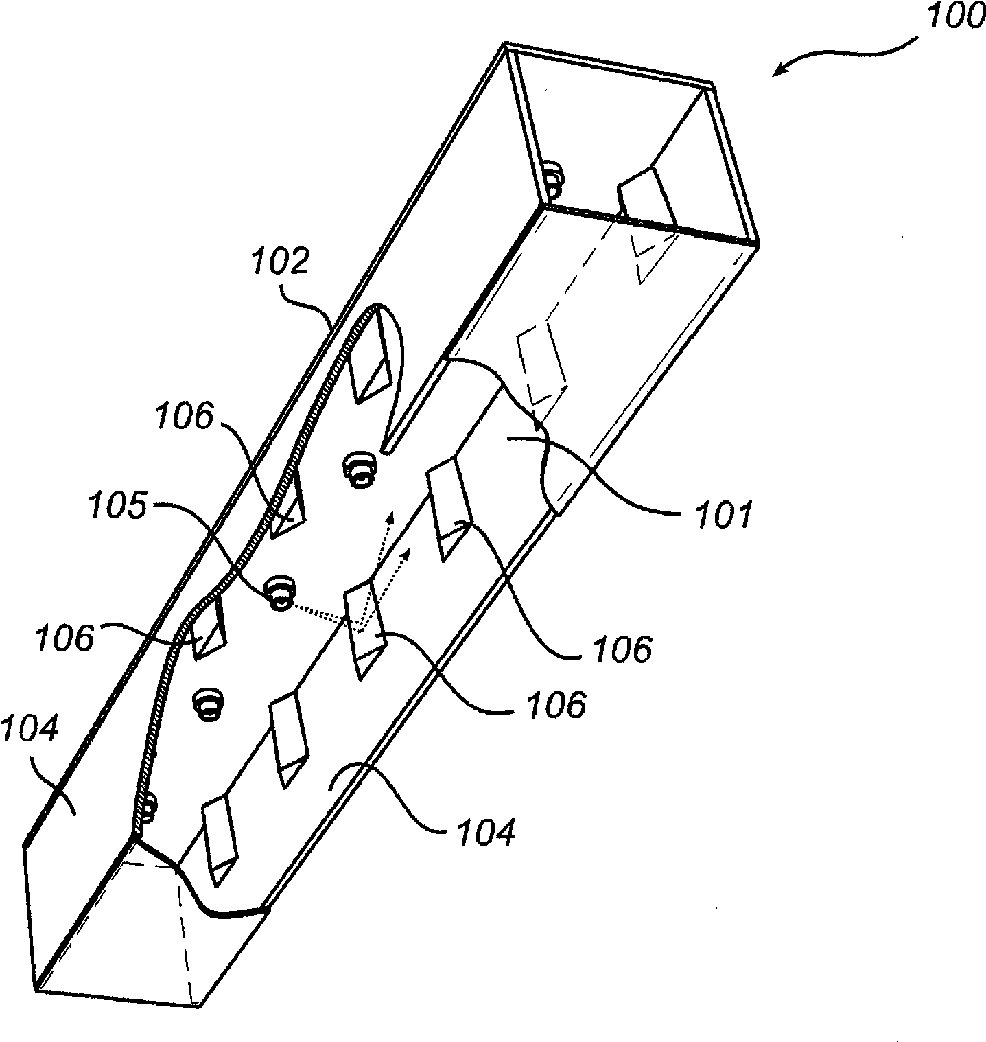
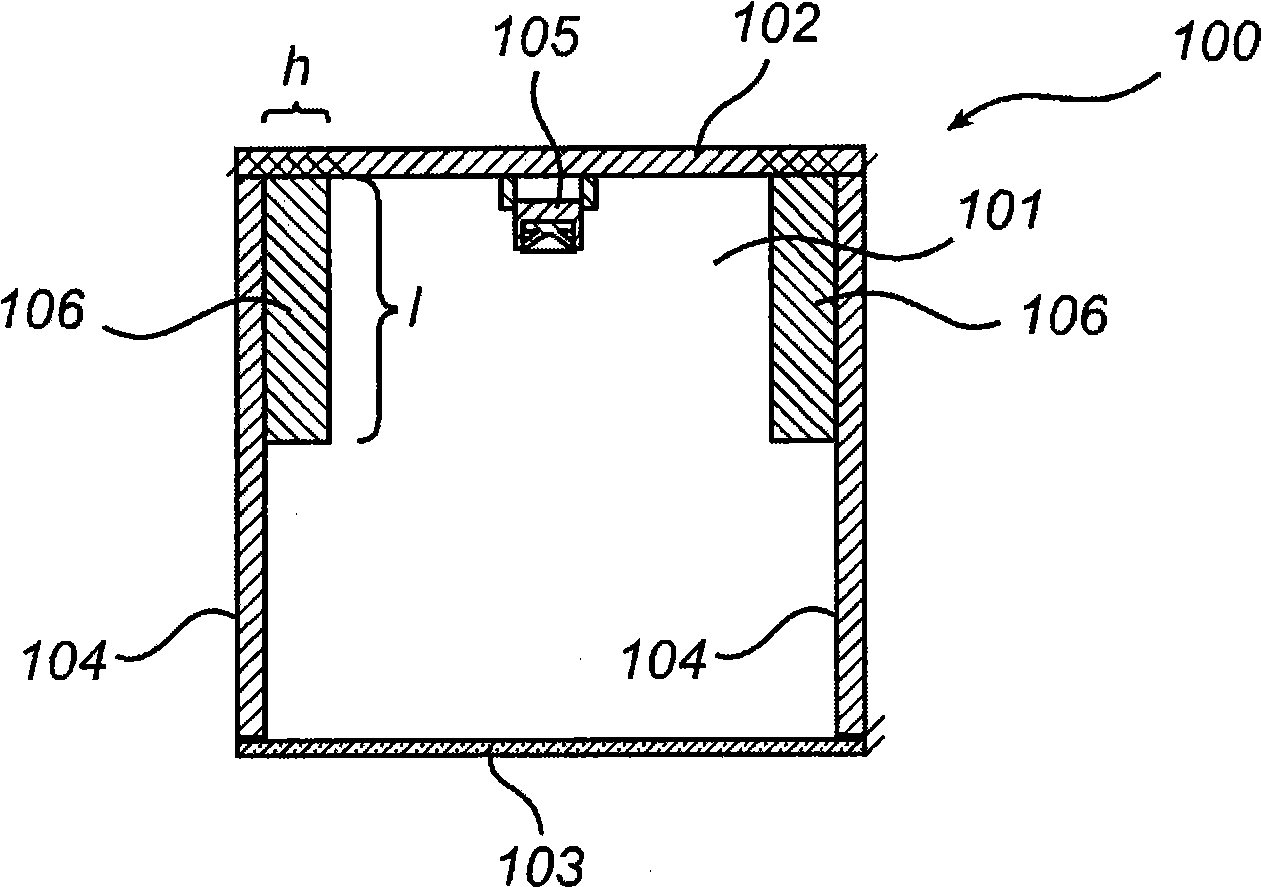
[0033] exist figure 1 and 2 An exemplary embodiment of a light emitting device 100 according to the present invention is shown in , comprising a housing 101 and an array of light emitting diodes 105 arranged in a row.

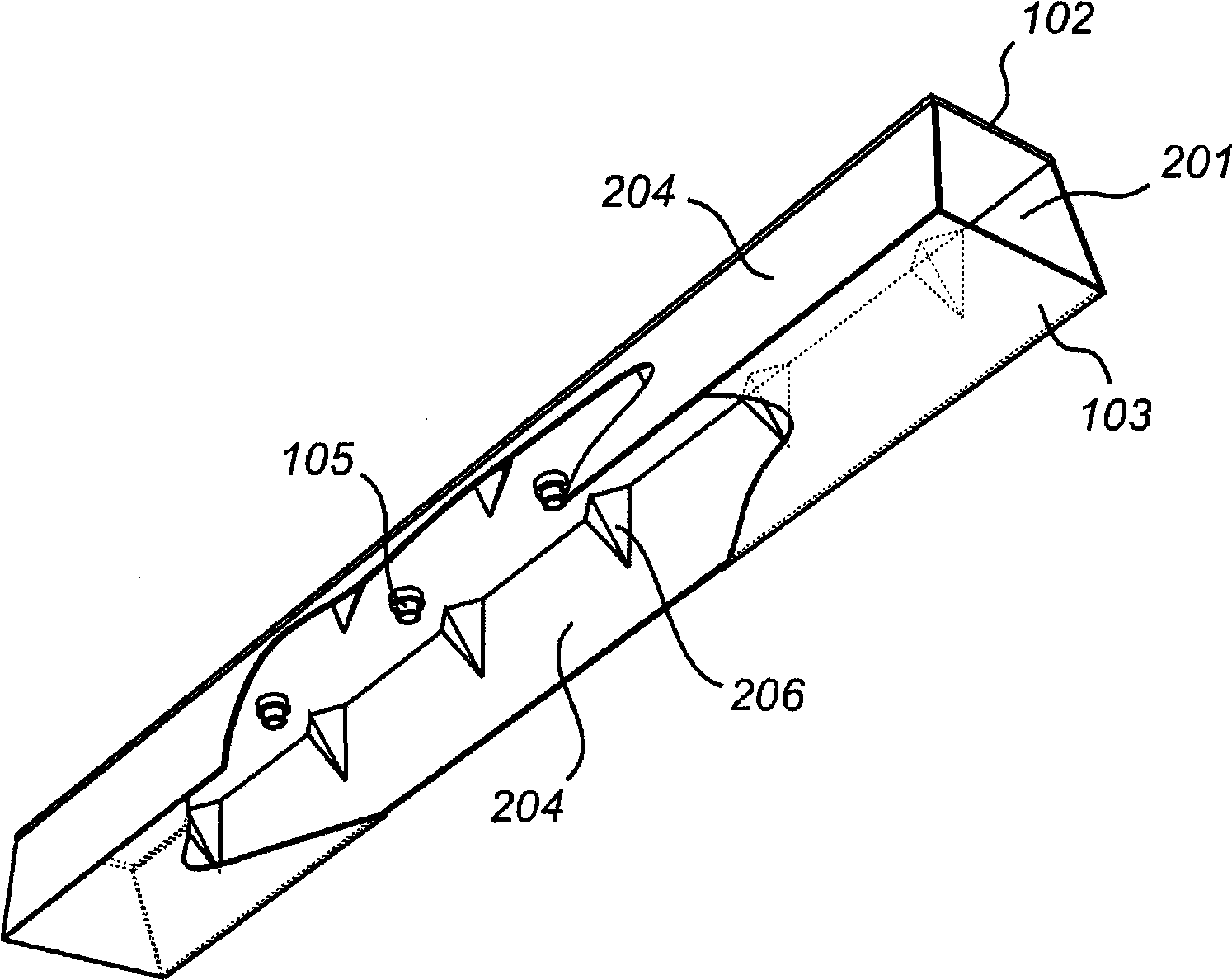
[0034] The housing 101 extends longitudinally and includes a top wall 102 , a diffuser surface 103 opposite thereto, and two elongated sidewalls 104 opposite to each other connecting the top wall and the diffuser surface.

[0035] The housing 101 itself represents a separately contemplated aspect of the invention, even if it is described as part of a light emitting device in the following description.

[0036] An array of spaced apart LEDs 105 is arranged on the top surface along the longitudinal extension of the housing, facing the diffusing surface 103 (ie inside the housing).

[0037] The top wall 102 extends longitudinally with the housing. The inner surface of the top wall 102 , ie the surface facing the diffusing surface 103 , is generally reflective,...


PUM


Abstract

A light emitting device (100) is provided that comprises a longitudinally elongated housing (101) comprising a top wall (102) and opposing diffusing surface (103), and two mutually opposing reflective longitudinally elongated sidewalls (104) connecting said top wall (102) with said diffusing surface (103). An array of mutually spaced apart light emitting diodes (105) arranged is in said housing along the longitudinal extension thereof, and at least one of said sidewalls (104) is provided with an array of mutually spaced apart light redirecting means (106). The light redirecting means reflect light away from the LED that emitted the light, leading to a good mixing of light from the LEDs in the array.

Description

field of invention [0001] The invention relates to a light-emitting device, which comprises a longitudinally elongated housing and an array of spaced-apart light-emitting diodes disposed in the housing along its longitudinal extension, the housing comprising a top wall and a diffusing surface opposite thereto, and two longitudinally elongated reflective side walls facing each other connecting the top wall and the diffusing surface. The invention also relates to this housing itself. Background technique [0002] Color mixing in interior lighting has become increasingly important in recent years. Color mixing with LEDs enables more extreme color changes in smaller volumes. [0003] Color mixing of the row of LEDs can be achieved, for example, by mixing the light from the LEDs on an optical diffuser. The distance between the LEDs presents a limitation on such lighting systems since the intensity should be kept at a substantially constant level along the direction of the row ...

Claims


Application Information

Patent Timeline
Patent Type & Authority Applications(China)
IPC IPC(8): F21V7/00F21Y101/02F21V15/01
CPCF21V15/01F21Y2103/003F21V7/00F21Y2101/02F21Y2103/10F21Y2115/10
Inventor P·G·H·科斯特斯L·R·C·沃曼斯
Owner KONINK PHILIPS ELECTRONICS NV
Why Eureka
Try Eureka