Rolling mill roll cooling device

A technology of cooling device and pressure roller device, which is applied in the direction of rolling, metal rolling, metal rolling, etc., can solve the problems of the adverse effect of accurate strip finish rolling temperature, difficult cleaning of the strip surface, etc., and achieve simple structure and low production cost. Low, the effect of improving the efficiency of use

Active Publication Date: 2010-06-09
CHINA NON-FERROUS METALS PROCESSING TECH CO LTD
View PDF0 Cites 10 Cited by
  • Summary
  • Abstract
  • Description
  • Claims
  • Application Information

AI Technical Summary

Problems solved by technology

[0003] In the cooling method described above, since the emulsion is directly sprayed onto the surface of the roll, a large amount of emulsion flows from the surface of the roll to the surface of the ingot. Due to the flow and volatilization of the emulsion on the surface of the ingot, a large amount of heat is bound to be taken away, resulting in rapid cooling of the hot-rolled ingot. , thus adversely affecting the precise strip finish rolling temperature; at the same time, the nozzle sprays the emulsion in an open space, and the oil mist formed by the emulsion injection also adversely affects the internal environment of the rolling mill and related equipment parts; and the strip A large amount of emulsion accumulation on the surface makes it difficult to clean the strip surface

Method used


Image

  • Rolling mill roll cooling device
  • Rolling mill roll cooling device
  • Rolling mill roll cooling device

Examples


Embodiment Construction

[0023] The present invention can be explained in more detail by the following examples, and the purpose of disclosing the present invention is intended to protect all changes and improvements within the scope of the present invention, but the present invention is not limited to the following examples;

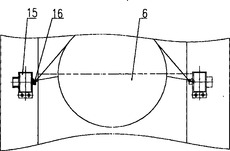
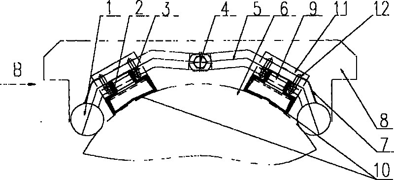
[0024] Such as figure 2 , image 3 , the rolling mill roll cooling device shown includes a cooler 2 for spraying emulsion and a pressing roll device.

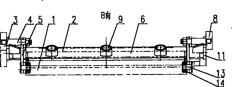
[0025] Such as Figure 4 , Figure 5 , Figure 6 As shown, the cooler 2 is arranged in a long box structure along the axial direction of the roll 6, and the two ends of the cooler 2 are provided with connecting plates 11, and the bolts a3 respectively pass through the bolt holes 12 on the connecting plate to firmly connect the cooler 2 to the roll bearing. The upper side of the seat 8; the bolt holes 12 on the connecting plate 11 are arranged as long holes, and the two bolt holes 12 are symmetrical to the central line of th...


PUM


Abstract

The invention relates to a rolling mill roll cooling device which comprises a cooler (2) used for jetting emulsion, and a compression roller device, wherein the cooler is fixedly connected at the side of the upper part of a roll bearing seat (8) by connecting plates (11) arranged at the two ends; the outer side of a box body of the cooler is provided with a water inlet (9), and the inner side thereof is provided with a water outlet (10); the compression roller device comprises a compression roller (1) and a support arm (5), wherein the compression roller is fixedly connected on the roll bearing seat by a bolt b (4) through the support arm, and the compression roller is evenly contacted with a roll (6) along the axial direction under the action of self weight; one cooler and one compression roller device are arranged in one group, and two groups of the coolers and compression roller devices are symmetrically arranged at the two sides of a vertical centre line of the roll; the emulsion firstly enters into the cooler through the water inlet and then evenly flows onto the surface of the roll through the water outlet; and a semi-closed space is formed by the compression rollers arranged at the two sides of the roll and a baffle (7) arranged on the support arm, so that a certain quantity of emulsified liquid is effectively maintained at the upper part of the roll, the roll is well cooled and lubricated, and the emulsified liquid flows away through a nick of the semi-closed space.

Description

technical field [0001] The invention relates to a cooling device applied on a rolling mill, in particular to a cooling device for a roll of a copper strip hot rolling mill. Background technique [0002] Such as figure 1 The traditional hot rolling mill roll cooling process shown in the figure uses nozzles (16) arranged sequentially on the nozzle beam (15) to spray emulsion-type cooling liquid, and the emulsion is directly sprayed onto the surface of the roll (6). [0003] In the cooling method described above, since the emulsion is directly sprayed onto the surface of the roll, a large amount of emulsion flows from the surface of the roll to the surface of the ingot. Due to the flow and volatilization of the emulsion on the surface of the ingot, a large amount of heat is bound to be taken away, resulting in rapid cooling of the hot-rolled ingot. , thus adversely affecting the precise strip finish rolling temperature; at the same time, the nozzle sprays the emulsion in an op...

Claims


Application Information

Patent Timeline
Patent Type & Authority Applications(China)
IPC IPC(8): B21B27/10
Inventor 陈向东张立新卫汉平侯定坤
Owner CHINA NON-FERROUS METALS PROCESSING TECH CO LTD
Why Eureka
Try Eureka