Elevating lever-type stop valve

A technology of stop valve and lifting rod, which is applied in the field of lifting rod type stop valve, can solve the problems of large opening and closing, reduced sealing performance, poor adjustment performance, etc., and achieves small opening and closing force, few components and good adjustment performance Effect

Inactive Publication Date: 2010-08-04
张福瑞
View PDF0 Cites 3 Cited by
  • Summary
  • Abstract
  • Description
  • Claims
  • Application Information

AI Technical Summary

Problems solved by technology

The disadvantages of the existing stop valves are that the fluid resistance is large, the force required for opening and closing is relatively large, it is not suita...

Method used


Image

  • Elevating lever-type stop valve
  • Elevating lever-type stop valve

Examples


Embodiment Construction

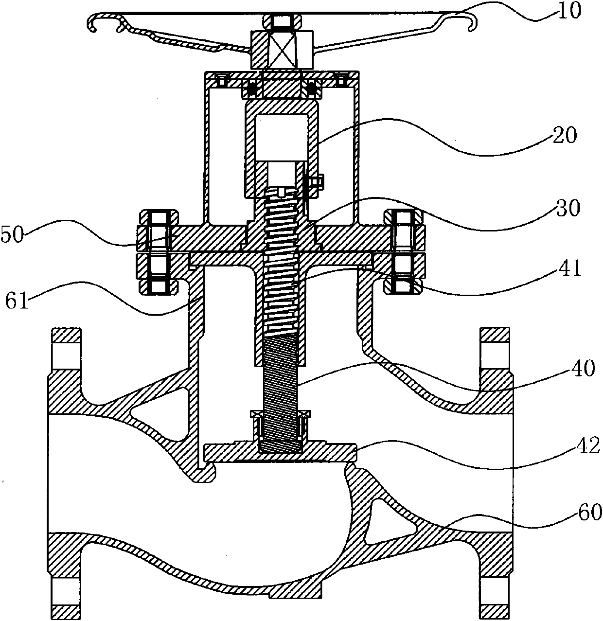
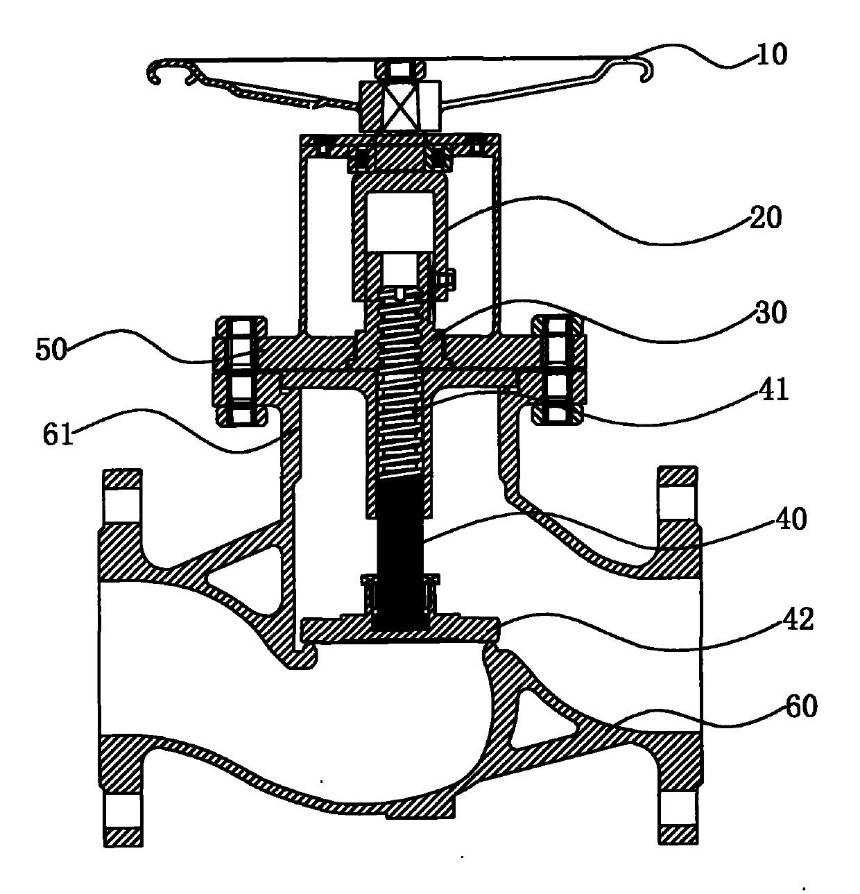
[0016] Such as figure 1 As shown, the lifting rod type globe valve has a valve seat 60 and a valve disc 42, and the valve disc is assembled on the lower end of the valve shaft 40 through a threaded connection. The valve shaft 40 is set in cooperation with a cap nut 30 through the driving thread 41, and the cap nut 30 is limited on a valve cap 50, and the cap nut 30 is driven by the handwheel driving handle 20, and the rotation of the cap nut 30 drives the valve through the driving thread 41. The shaft 40 moves up and down to realize the opening and closing of the fluid channel in the valve seat 60 . A hole frame 61 is arranged on the upper part of the valve seat 60, and a valve cover 50 is used for flange sealing outside the hole frame mouth. The opening of the chassis is embedded, and the cover nut 30 is limitedly installed in the opening of the valve cover. A shaft sleeve is also installed in the hole frame, and the upper part of the shaft sleeve has a top cover, and the e...


PUM


Abstract

The invention discloses an elevating lever-type stop valve, which comprises a valve seat and a valve flap, wherein the valve flap is arranged at a lower end of a valve shaft. The elevating lever-type stop valve is characterized in that: the valve shaft is matched with a cap nut via drive threads; the cap nut is limited on a valve cap and is driven by a handwheel driving handle; and the rotation of the cap nut drives the valve shaft to move up and down by means of the drive threads so as to open and close a fluid channel in the valve seat. The elevating lever-type stop valve has the advantages of rational design, less parts and components, convenient assembly, high precision, excellent adjusting performance, small opening and closing force, convenient repair and maintenance, and suitability for different fluid media.

Description

technical field [0001] The invention belongs to a shut-off valve for fluid medium, and in particular relates to a lifting rod-type shut-off valve which is labor-saving and suitable for a wide range of media. Background technique [0002] The globe valve is a forced sealing valve. When the valve is closed, pressure must be applied to the disc to force the sealing surface not to leak. When the fluid medium enters the valve six from the bottom of the disc, the resistance that the operating force needs to overcome is the friction force between the valve stem and packing and the thrust generated by the pressure of the medium. The force to close the valve is greater than the force to open the valve, so the valve The diameter of the stem should be large, otherwise the failure of the stem to bend will occur. In recent years, since the emergence of self-sealing valves, the flow direction of the medium of the globe valve has changed from the top of the disc to the valve cavity. The ...

Claims


Application Information

Patent Timeline
IPC IPC(8): F16K1/04F16K31/60F16K41/00F16K1/48
Inventor 张福瑞
Owner 张福瑞
Why Eureka
Try Eureka