Turbine device with changeable runner

A turbine and flow channel technology, applied in mechanical equipment, engine components, combustion engines, etc., to achieve the effects of low cost, simple structure and improved efficiency

Inactive Publication Date: 2011-01-19
KANGYUE TECH
View PDF5 Cites 7 Cited by
  • Summary
  • Abstract
  • Description
  • Claims
  • Application Information

AI Technical Summary

Problems solved by technology

[0005] The problem to be solved by the present invention is to provide a variable channel turbine device for the limitations of the current variable cross-section turbocharger, which can effectively adjust the flow entering the turbine volute by setting a partition plate in the turb

Method used


Image

  • Turbine device with changeable runner
  • Turbine device with changeable runner
  • Turbine device with changeable runner

Examples


Embodiment 1

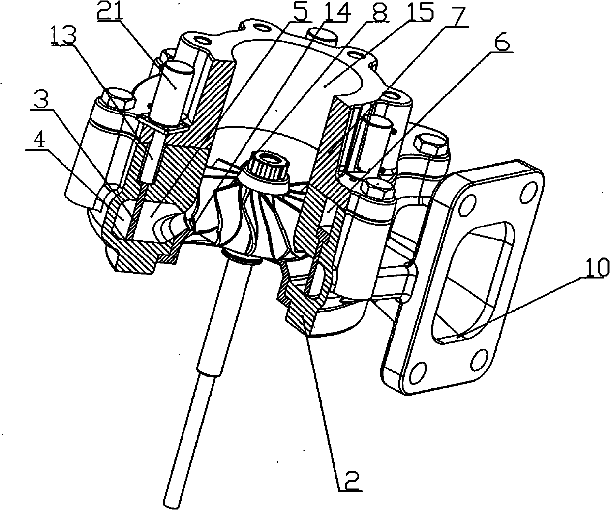
[0033] Embodiment 1, as attached figure 1 As shown, a variable channel turbine device includes a turbine volute 2, a turbine volute cover plate 7, and a turbine impeller 8. The turbine volute 2 is provided with a turbine volute flow channel 1, and the turbine volute flow channel 1 is There is a turbine volute inlet 10 and a turbine volute outlet 15, and the high-temperature exhaust gas discharged from the engine directly enters the turbine volute flow channel 1 along the turbine volute inlet 10 to provide power to the turbine impeller 8, in order to increase The intake energy at the turbine end sets the turbine volute channel 1 as a tapered type.

[0034] The spacer plate 3 of annular structure is arranged in the described turbine volute channel 1, and spacer plate 3 is positioned in the whole turbine volute channel 1, and described spacer plate 3 can move along the axial direction of turbine volute 2, and the spacer The board 3 is in drive connection with the control mechani...

Embodiment 2

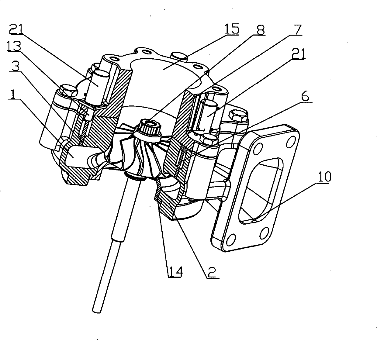
[0044] Embodiment 2, as attached Figure 4As shown, the control mechanism 9 in Embodiment 1 can also be a hydraulic cylinder 21 , and the hydraulic rod of the hydraulic cylinder 21 is connected to the threaded rod 13 .

[0045] The height of the hydraulic cylinder 21 is limited by the height of the turbine volute flow passage 1, and the hydraulic cylinder 21 is controlled by a hydraulic pump connected to the engine, so as to effectively adjust the axial movement of the partition plate 3 in the annular groove 6 according to the engine working conditions;

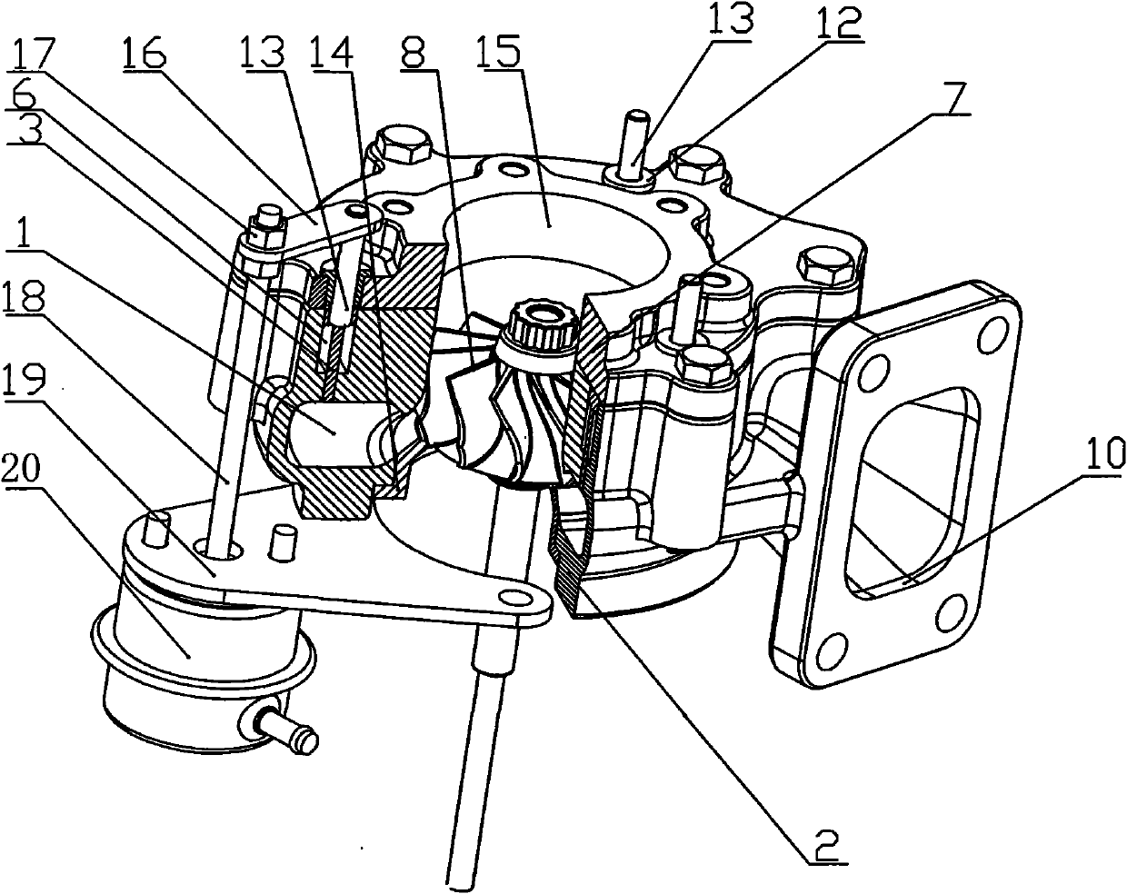
[0046] When the engine is in the low speed range, the partition plate 3 is in a closed state driven by the hydraulic cylinder 21, and the engine exhaust gas entering from the turbine volute inlet 10 only flows along the direction of the inner flow 5, thereby pushing the turbine impeller 8 rotates, at this time, the outer runner 4 is in a closed state and no exhaust gas will flow through it.

[0047] Such as Figure 5 As sho...


PUM


Abstract

The invention discloses a turbine device with a changeable runner. The turbine device comprises a turbine volute, a turbine volute casing cover plate and a turbine wheel, wherein the inside of the turbine volute casing is provided with a turbine volute casing runner; a turbine volute casing gas inlet and a turbine volute casing gas outlet are arranged on the turbine volute casing runner; and a partition board is arranged in the turbine volute casing runner, and the partition board can move along the axial direction of the turbine volute casing. In the turbine device of the invention, the partition wall capable of moving axially is arranged in the turbine volute casing runner, thus the turbine volute casing runner can have different runner sections, the energy of the exhaust gas discharged from the engine can be utilized extremely and the turbines efficiency can be effectively increased. The turbine device with the changeable runner of the invention which contains the partition wall capable of moving axially has simple structure and low cost, is reliable and is easy to realize.

Description

technical field [0001] The invention relates to a supercharging device for an internal combustion engine, in particular to a variable channel turbine device for a turbocharger for a vehicle, which belongs to the field of internal combustion engines. Background technique [0002] In recent years, with the improvement of engine performance and increasingly stringent emission regulations, people have put forward higher requirements for the performance of turbochargers that can balance the high and low speeds of vehicle engines. However, because the traditional single-channel turbocharger is suitable for an equal-pressure supercharging system, the turbocharger exhibits unequal efficiency at high and low speeds, and the reliability of the turbocharger is relatively poor. Therefore, in order to meet the performance requirements of the engine in the full range of operating conditions, variable cross-section turbocharging technology has received more and more attention, and has grad...

Claims


Application Information

Patent Timeline
IPC IPC(8): F02B37/22F01D17/10F01D25/24
CPCY02T10/144Y02T10/12
Inventor 王航袁道军王艳霞朱智富李永泰宋丽华张建国
Owner KANGYUE TECH
Why Eureka
Try Eureka