Catch

A technology of stopper and position element, applied in the direction of mechanical drive clutch, clutch, mechanical equipment, etc., can solve problems such as weakening of strength, and achieve the effect of reducing ease, increasing number, and simple manufacturing

Active Publication Date: 2011-02-02
SCHAEFFLER TECH AG & CO KG
View PDF4 Cites 12 Cited by
  • Summary
  • Abstract
  • Description
  • Claims
  • Application Information

AI Technical Summary

Problems solved by technology

The stepping notch leads to an additional weakening of the synchronizing body or requires an axially wider synchronizing body in order to integrate the function

Method used


Image

  • Catch
  • Catch
  • Catch

Examples


Embodiment Construction

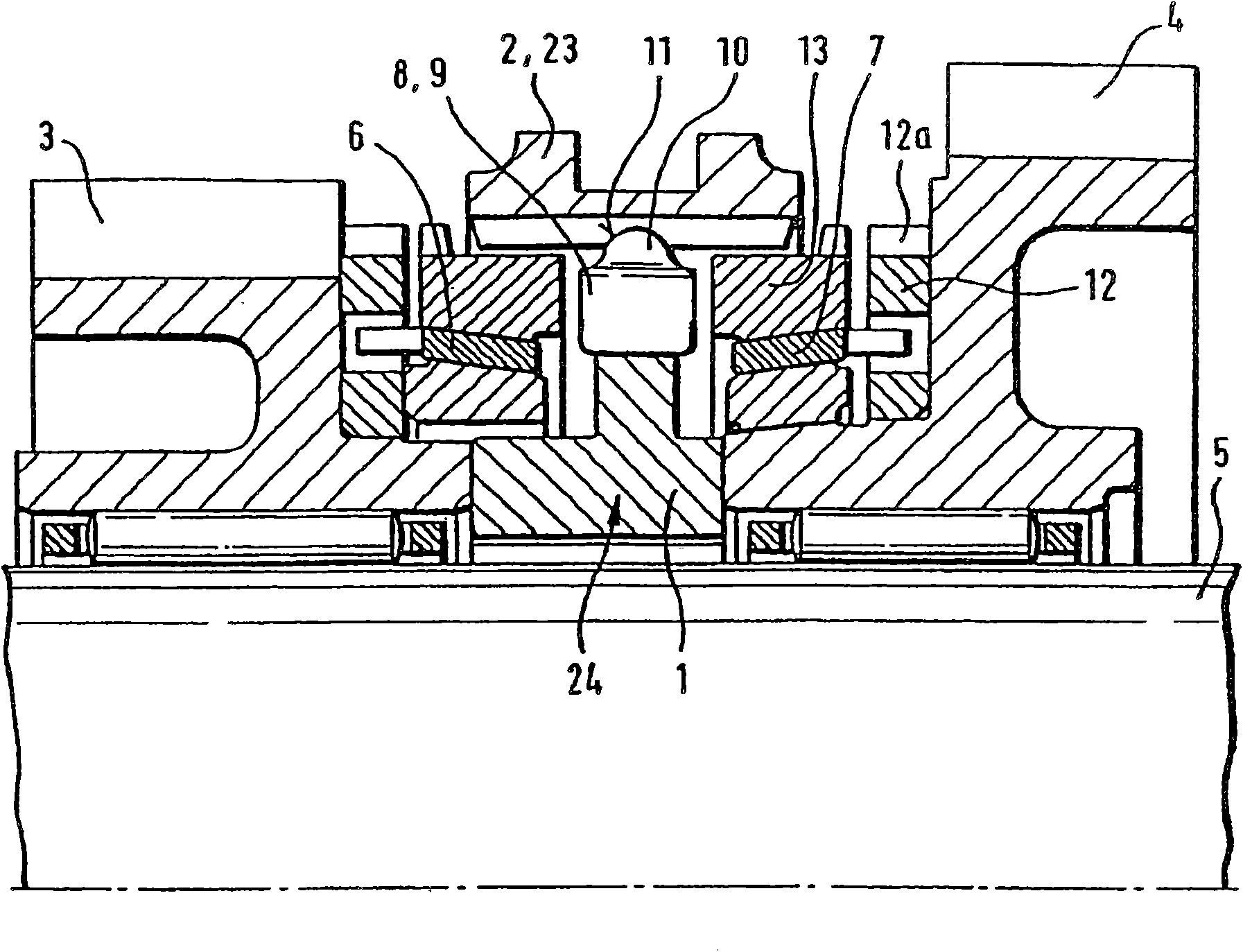
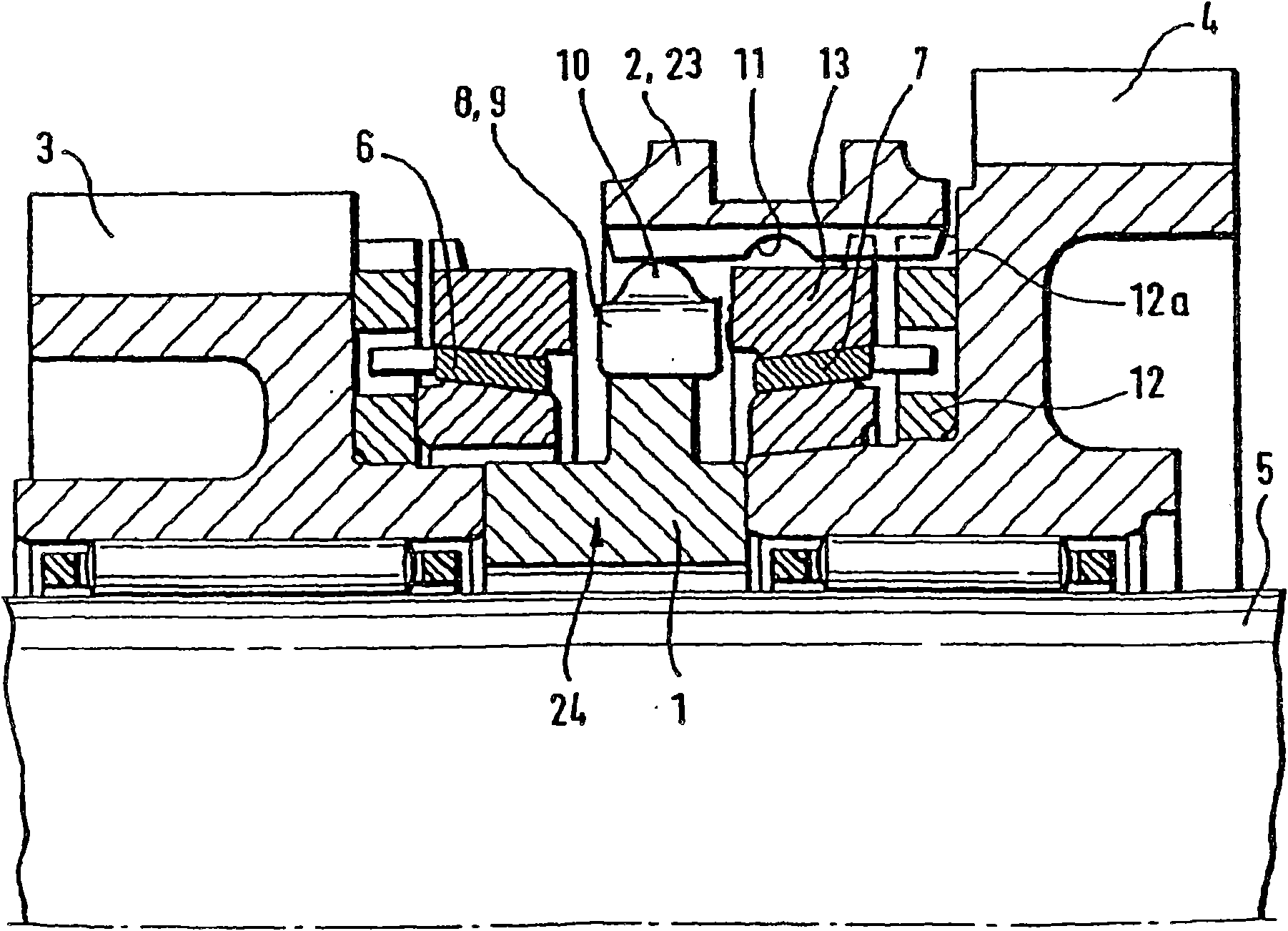
[0034] Figure 1a and 1b A synchronizing clutch 24 is shown, which consists of a synchronizing body 1 and a shifting sleeve 2 for selectively engaging the gearwheels 3 and 4 . The gearwheels 3 , 4 are mounted rotatably but fixed in the longitudinal direction on the selector shaft 5 . The synchronizing body 1 is mounted in a rotationally fixed and longitudinally fixed manner on the shifting shaft 5 and carries a transmission component 23 in the form of a shifting sleeve 2 on the outer circumference of the synchronizing body 1 . The shifting sleeve 2 is arranged on the synchronizing body 1 by means of a toothing in a rotationally fixed manner relative to the synchronizing body 1 and thus relative to the shifting shaft 5 , but selectively displaceable in the longitudinal direction in the direction of the gearwheel 3 or 4 . . On each side of the synchronizing body 1 a set of synchronizing rings 6 , 7 is arranged in the longitudinal direction between the synchronizing body 1 and...


PUM


Abstract

The invention relates to a catch (6) of a synchronization device (27) that can be axially displaced in the installed state with regard to a synchronous body (1) comprising teeth at the outer circumference thereof, wherein the catch (6) comprises a catch element (8) acted on by an engagement element (15) for engaging in a rest position and a housing (14) having an approximately rectangular radial surface (16) having axial edges (17, 18) aligned outward and side edges (19, 20) oriented in the circumferential direction, wherein the catch element (8) is disposed in the interior of the radial surface (16), the wings (21, 22) being formed flush with the radial surface (16) as seen in the radial direction, and the axial width of the wings (21, 22) being smaller than the minimal axial width of the radial surface (16), and a method for producing the same.

Description

technical field [0001] The invention relates to a locking element for locking a first transmission component on a second transmission component in at least one adjustment position. The locking element can be used in a synchronization device and can be axially displaceable on the outer circumference of the synchronizing body with teeth in the assembled state, wherein the locking element has: a catch loaded with a spring element Positioning element for locking in a certain adjustment position; and a housing with an outwardly directed, substantially rectangular radial face having an axial edge and being oriented in the circumferential direction side, wherein the locking element is arranged inside the radial face. Background technique [0002] It is known to a person skilled in the art that such a retaining element is used in various applications in a transmission of a motor vehicle. The locking element, for example, locks the movable transmission element in a shift position o...

Claims


Application Information

Patent Timeline
Patent Type & Authority Applications(China)
IPC IPC(8): F16D23/06
CPCF16D23/06F16D2023/0618
Inventor 拉尔夫·博斯纳霍尔格·格雷斯曼马库斯·施珀尔
Owner SCHAEFFLER TECH AG & CO KG
Why Eureka
Try Eureka