Printer structure

A technology for printers and casings, applied in typewriters, printing, etc., can solve problems such as printer jams, and achieve the effect of avoiding paper jams

Active Publication Date: 2011-04-06
EDAN INSTR
View PDF5 Cites 13 Cited by
  • Summary
  • Abstract
  • Description
  • Claims
  • Application Information

AI Technical Summary

Problems solved by technology

[0003] In order to solve the technical problem of printer jamming in the prior art, the present invention provides a printer structure

Method used


Image

  • Printer structure
  • Printer structure
  • Printer structure

Examples


Embodiment Construction

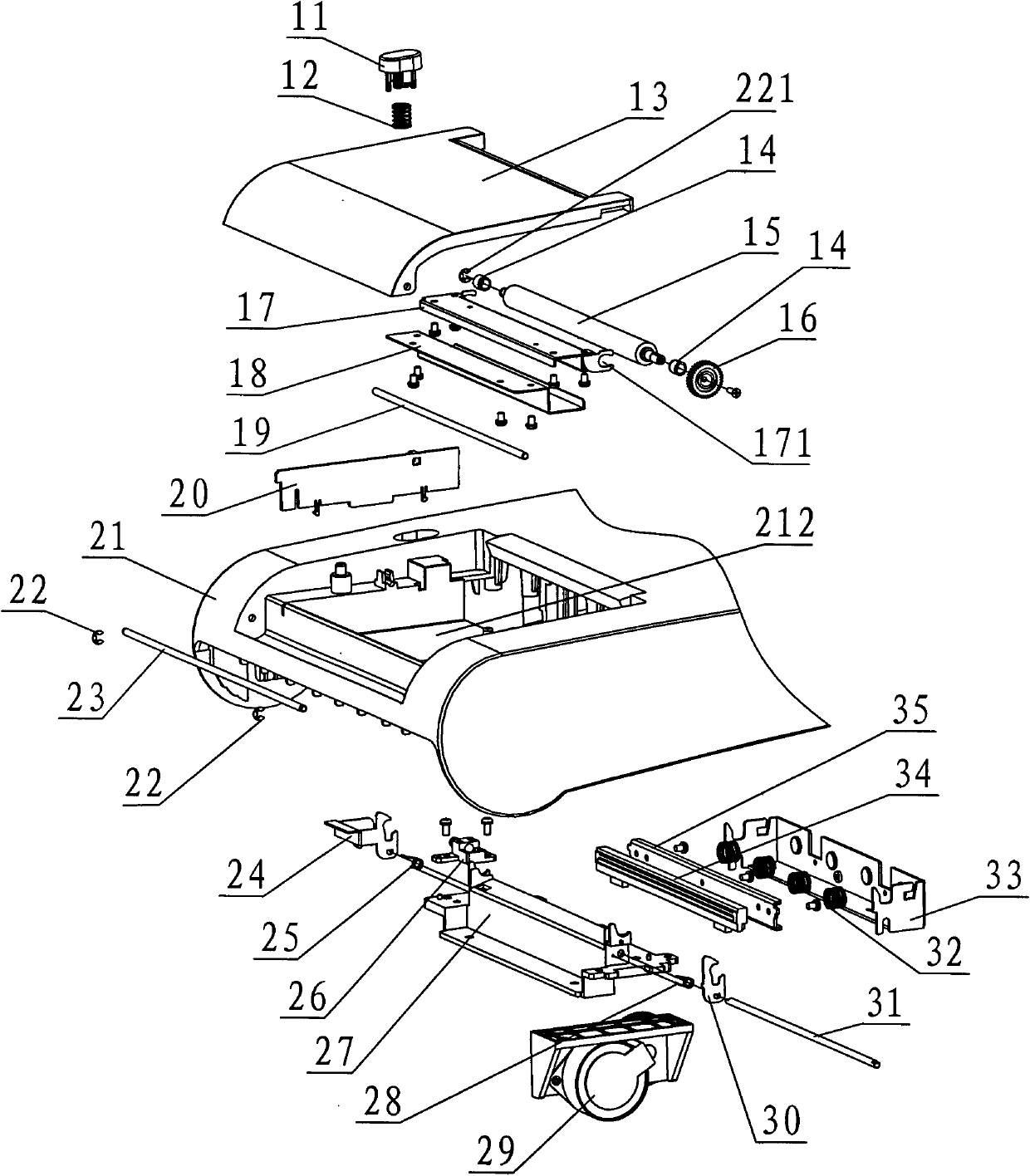
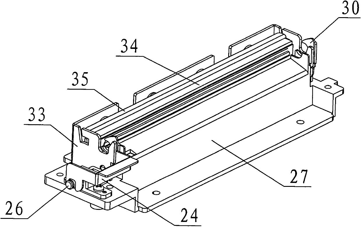
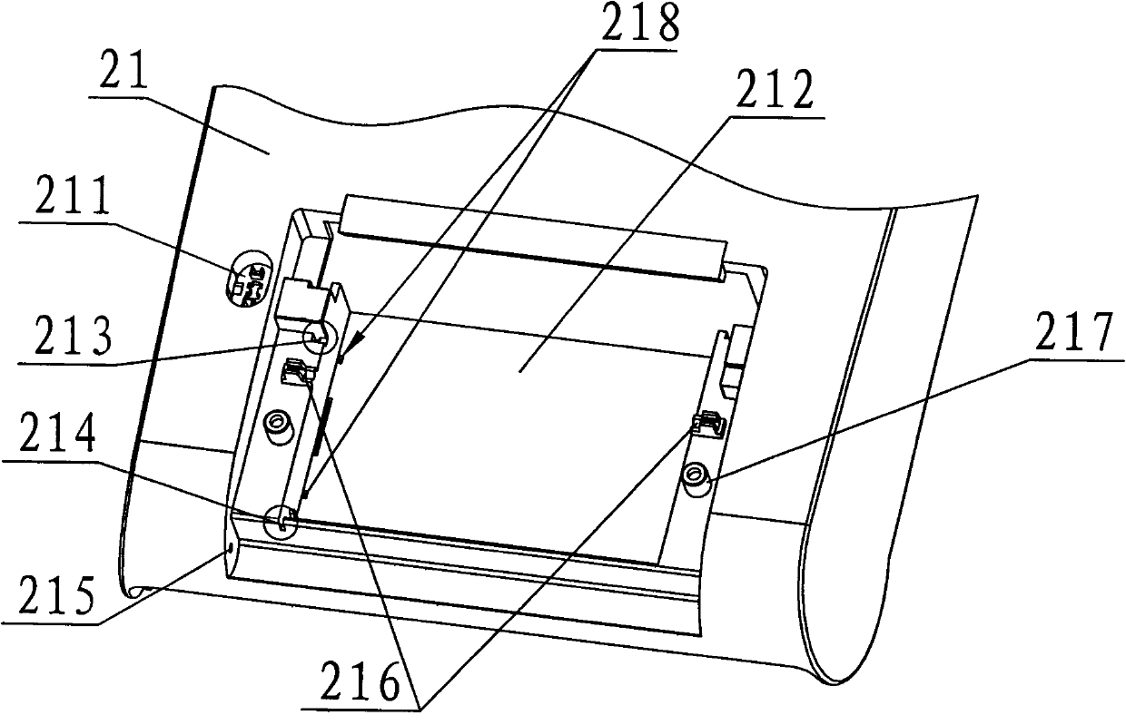
[0027] Such as Figure 1 to Figure 12 As shown, a printer structure includes a cover body 13, a roller 15, a limiting device, a housing 21, a thermal head 34, and a base device, the roller 15 is installed at the limiting device, and the The roller 15 can rotate relative to the limiting device; the limiting device is installed on the inner surface of the cover 13, the thermal head 34 is installed at the base device, and the thermal head 34 Can move relative to the base device; the printer structure also includes an elastic device that provides a reaction force to the thermal head 34, the housing 21 is provided with a paper storage bin 212, and the base device is installed on the housing At the body 21, the cover body 13 is movably connected to the housing 21; when printing, the roller 15 and the thermal head 34 are in contact with each other and kept on the same horizontal line; the printer structure also includes A power drive device that makes the roller 15 rotate. When the...


PUM


Abstract

The invention provides a printer structure. When printing is performed, a roller applies a driving force on a thermal head and ensures the thermal head to move a certain distance backward, then an elastic device applies an opposite acting force on the thermal head to ensure that the thermal head closely sticks to the roller; and the flatness can be automatically adjusted through the opposite acting force of the elastic device. Therefore, the thermal head and the roller can be at the same level and the paper jamming phenomenon in the printing process can be avoided.

Description

【Technical field】 [0001] The invention relates to a printer structure, in particular to a printer structure used in medical equipment. 【Background technique】 [0002] Printers have been used in various fields, and they are also widely used in the field of medical equipment; for example, when people go to the hospital for physical examination, doctors need to use the printer on the medical equipment to print out waveforms for diagnosis and analysis, so as to judge the body of the examinee It can be seen that the application of printers in the medical field also plays an extremely important role, but the structure of printers currently used in the market has more serious paper jams during the printing process. 【Content of invention】 [0003] In order to solve the technical problem of printer jamming in the prior art, the invention provides a printer structure. [0004] The invention provides a printer structure, including a cover body, a roller, a limit device, a housing, a...

Claims


Application Information

Patent Timeline
Patent Type & Authority Applications(China)
IPC IPC(8): B41J3/00B41J2/32
Inventor 钟光耀王功华张雷郭传喜
Owner EDAN INSTR
Why Eureka
Try Eureka