
Multidirectional conveying guider for flaky materials

A flake, guide technology, applied in the field of guide, can solve the problems of motor control error, high precision, difficult maintenance and so on

Inactive Publication Date: 2014-06-25
广州智萃电子科技有限公司
View PDF9 Cites 4 Cited by
  • Summary
  • Abstract
  • Description
  • Claims
  • Application Information

AI Technical Summary

Problems solved by technology

This application has the following problems: 1. When it is necessary to change the transmission direction, a stepping motor and two lifting magnets need to cooperate with each other at the same time, that is, in the control program, three actions need to be controlled, resulting in more complicated program control. Error prone, poor stability
2. It can be seen from the above working process that only the reversing between the two side channels involves many transmission components. In order to ensure the normal lifting of the guide blades, both ends of the guide body need rack and pinion transmission. The reversing between the two side passages of the above-mentioned guide requires a large number of transmission parts, resulting in complex structure of the whole guide, difficult maintenance and high production cost
3. The driving mode of the motor is mainly through the direct transmission of the rack and pinion, which is equivalent to one rotation of the gear. The displacement of the rack and the entire mechanism is the pitch circle circumference of a gear. However, there must be errors in the control of the motor, resulting in inability to Realize precise displacement control
In order for the guide to convey the sheet along the three paths, three reversing blades must cooperate with each other. The cooperation of multiple reversing blades requires high precision, which increases production and maintenance costs, and increases the structure. Complexity and instability, greatly increasing the chance of paper jams

Method used


Image

  • Multidirectional conveying guider for flaky materials
  • Multidirectional conveying guider for flaky materials
  • Multidirectional conveying guider for flaky materials

Examples


Embodiment Construction

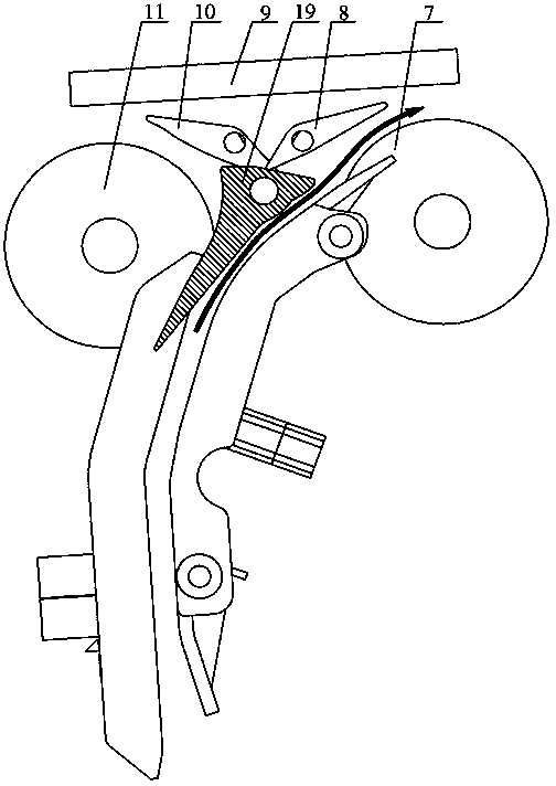
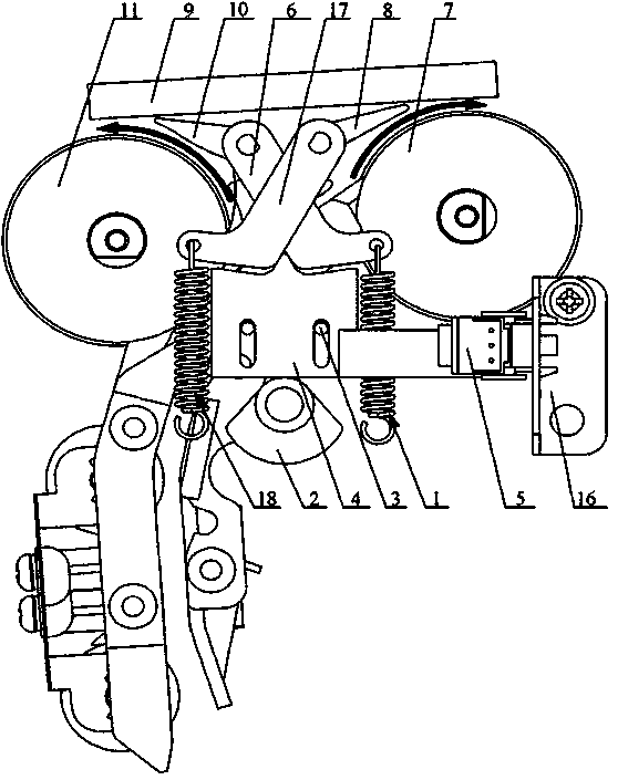
[0020] A multi-directional conveying guide for sheets, such as Figure 4-8 As shown, it includes a channel plate assembly 1 forming a multi-directional channel, a reversing vane assembly 2 that closes or opens different channels on the channel plate assembly 1, and a power drive assembly 3 that drives the reversing vane assembly 2 to move; the reversing vane assembly 2 includes a reversing vane shaft 21 that rotates around its own axis, and a reversing vane 22 that is mounted on the reversing vane shaft 21 and can close or open different passages on the channel plate assembly 1, and one end of the reversing vane shaft 21 is fixed on On the equipment frame, the other end is connected with the two-way electromagnet 38 of the power drive assembly 3; Motor 33 and screw rod 34, power motor 33 and screw rod 34 are connected to transmit motion through gear pair 35, and screw rod 34 is sleeved with screw rod seat 36 that moves along the axis of screw rod rod 34 as screw rod 34 rotates...


PUM


Abstract

The invention discloses a multidirectional conveying guider for flaky materials. The multidirectional conveying guider comprises a channel plate assembly and a reversing blade assembly. Multidirectional channels are formed on the channel plate assembly, the different channels on the channel plate assembly can be closed or opened by the reversing blade assembly, the reversing blade assembly is driven by a bidirectional electromagnet, the bidirectional electromagnet is driven by a power motor via a screw, and accordingly an optional channel on the channel plate assembly can be opened. The multidirectional conveying guider has the advantages that the bidirectional electromagnet and the power motor are matched with each other, so that the multidirectional channels can be selected, the multidirectional conveying guider is simple in structure and small in size, the work complexity can be greatly lowered, and the production and maintenance costs can be effectively reduced; the bidirectional electromagnet can work safely and quickly, and accordingly the multidirectional conveying guider is favorable for improving the work efficiency; movement is transmitted via the screw, so that the control precision of the multidirectional conveying guider can be effectively improved, and influence of errors of the motor can be prevented.

Description

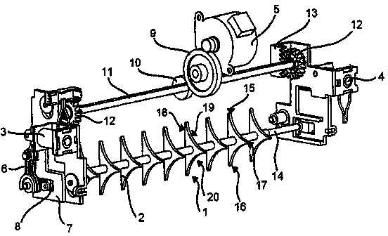
technical field [0001] The invention relates to a guide, in particular to a guide for conveying sheets in multiple directions. Background technique [0002] With the rapid development of modern social economy, in order to improve the work efficiency of financial business, many self-service equipment have appeared to replace manual services. The diversification of financial services requires these self-service devices to have multiple functions to meet business needs, such as being able to transport sheets such as tickets or cards in multiple directions. [0003] Such as figure 1 As shown, the Chinese patent application with the application number 200880101729.0 discloses a three-way guide for turning sheet-like media. The guide has three driving devices, which are respectively a stepping motor 5 and two lifting magnets 3, 4. When the two side channels are reversing, the working process is as follows: the stepping motor 5 drives the driving rod 11 to rotate through the two...

Claims


Application Information

Patent Timeline
IPC IPC(8): B65H29/58
CPCB65H29/58B65H2404/632
Inventor 罗灿裕
Owner 广州智萃电子科技有限公司
Learn More