
Driving-and-transmission integrated musculoskeletal driver and performance testing device thereof

A muscle driver and drive transmission technology, applied in the field of bionic engineering, can solve the problems of dead zone, effective tension reduction, lack of constant volume, etc., and achieve the effects of convenient operation, low manufacturing cost and simple device structure

Pending Publication Date: 2018-02-02
JILIN UNIV
View PDF11 Cites 3 Cited by
  • Summary
  • Abstract
  • Description
  • Claims
  • Application Information

AI Technical Summary

Problems solved by technology

However, the output pulling force of McKibben type pneumatic artificial muscle will be affected by friction and inelastic deformation of rubber. The inelastic deformation of the pneumatic artificial muscle causes hysteresis and pressure dead zone during the working process, which leads to the reduction of the effective tension generated by the inflation contraction, and the efficiency is low; in addition, the muscle needs to maintain a constant volume during the contraction, so any muscle in When contracting, it needs to expand in the direction orthogonal to its line of action, and the tissue that resists this expansion may mediate how the shape of the muscle changes, and ultimately determine the transmission ratio of the muscle's operation, but this McKibben-type pneumatic artificial muscle array lacks a constant volume. control, ignoring the significance of dynamic changes in muscle shape

Method used


Image

  • Driving-and-transmission integrated musculoskeletal driver and performance testing device thereof
  • Driving-and-transmission integrated musculoskeletal driver and performance testing device thereof
  • Driving-and-transmission integrated musculoskeletal driver and performance testing device thereof

Examples


Embodiment Construction

[0034] The present invention is described in detail below in conjunction with accompanying drawing:

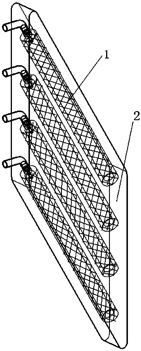
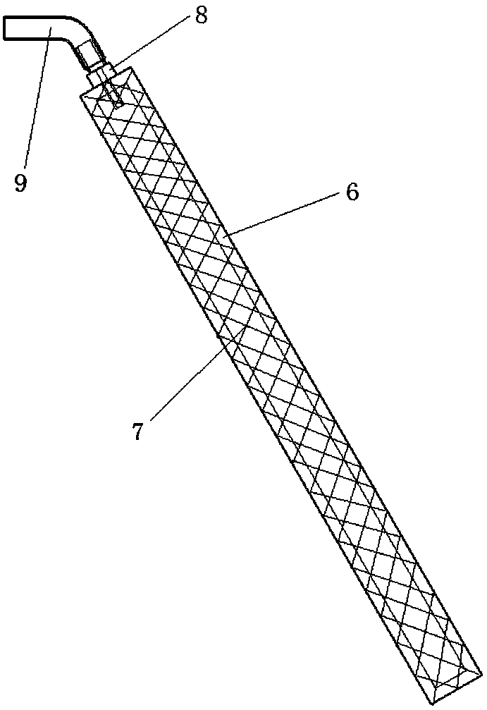
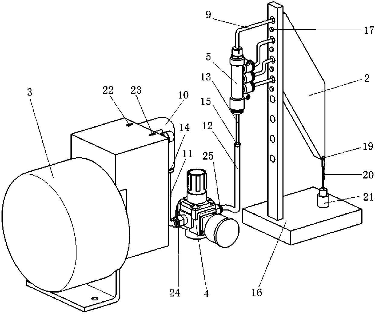
[0035] Such as figure 1 , figure 2 , Figure 9 As shown, an imitation skeletal muscle driver with drive and transmission integration includes four imitation muscle fiber drive units 1 encapsulated in a flexible matrix 2, and each imitation muscle fiber drive unit 1 includes an inner diameter of 6 mm, an outer diameter of 10 mm, and a length of It is a 120mm hollow cylindrical elastic inner hose 6 with both ends closed. The elastic inner hose 6 is made of elastomer material silicone, from the center of one end of the elastic inner hose 6 to the end of the elastic inner hose 6 Insert a first variable-diameter joint 8 into the inner cavity and seal the joint between the first variable-diameter joint 8 and the elastic inner hose 6 with a silicone adhesive, and a nylon braided mesh sleeve 7 is set on the outer wall of the elastic inner hose 6 , and use cable ties to tighten the...


PUM

PropertyMeasurementUnit
The inside diameter ofaaaaaaaaaa
Outer diameteraaaaaaaaaa

Abstract

The invention discloses a driving-and-transmission integrated musculoskeletal driver and a performance testing device thereof. The musculoskeletal driver is composed of muscle fiber imitated driving units and a flexible matrix. The shape of the flexible matrix and structures and spatial arrangement of the muscle fiber imitated driving units are designed according to the spatial structure of a realmuscle, thereby forming a muscle fiber imitated driving unit matrix and packaging in the flexible matrix. For testing function of the musculoskeletal driver, a driving air source is supplied to the musculoskeletal driver by an air pump, a pressure regulator and a pipeline. A load is applied to the musculoskeletal driver, thereby making the muscle fiber imitated driving units contract. In each contraction, motion of the musculoskeletal driver is recorded by a digital camera, and a relation among thickness of the musculoskeletal driver, the rotation magnitude of the muscle fiber imitated driving units and a load is measured, thereby obtaining a transmission ratio of the musculoskeletal driver. The performance testing device is used for verifying the driving-and-transmission integrated performance of the musculoskeletal driver and an automatic speed change characteristic according to load change.

Description

technical field [0001] The invention belongs to the technical field of bionic engineering, relates to a power drive device of a robot, and in particular relates to an imitation skeletal muscle driver with integrated driving and transmission and a performance testing device thereof. Background technique [0002] Biomechanical studies have shown that skeletal muscles regulate output force and speed through changes in the muscle fiber feather angle (the angle between the muscle fiber and the muscle force line). When subjected to a low load, the thickness of the muscle contraction increases, the feather angle increases after the muscle fiber rotates, the muscle output force decreases, and the movement speed increases; when the muscle is subjected to a high load, its width increases, the fiber rotation reduces the feather angle, and the movement The speed is reduced and the output force is increased. This shows that the human skeletal muscle is both a drive unit and a transmissi...

Claims


Application Information

Patent Timeline
IPC IPC(8): G01M13/00
CPCG01M13/00
Inventor 任雷刘春宝丁鹏钱志辉任露泉
Owner JILIN UNIV
Learn More