Stator wire embedding mold and stator wire embedding device

A technology for inserting wire molds and stators, which is used in electromechanical devices, manufacturing motor generators, and electrical components, etc., can solve the problems of decreased insulation performance of enameled wires, higher requirements for manual skills, and scrapped motors.

Active Publication Date: 2017-04-26
CHANGZHOU JINKANG PRECISION MECHANISM
View PDF5 Cites 4 Cited by
  • Summary
  • Abstract
  • Description
  • Claims
  • Application Information

AI Technical Summary

Problems solved by technology

[0002] The stator is an important part of the motor. There are many occasions where the motor is used in industrial products. Many electrical products are used as the driving power source. The stator is the main part of the motor. The stator is mainly composed of coils and iron cores. The traditional stator processing process is mostly the The copper wire is wound on the wire mold, and then the copper coil is manually embedded into the stator core. This processing method has many disadvantages: low efficiency; high requirements for manual skills, and the artificial embedded wire is relatively loose, which affects the stator core. perf

Method used


Image

  • Stator wire embedding mold and stator wire embedding device
  • Stator wire embedding mold and stator wire embedding device
  • Stator wire embedding mold and stator wire embedding device

Examples


Embodiment Construction

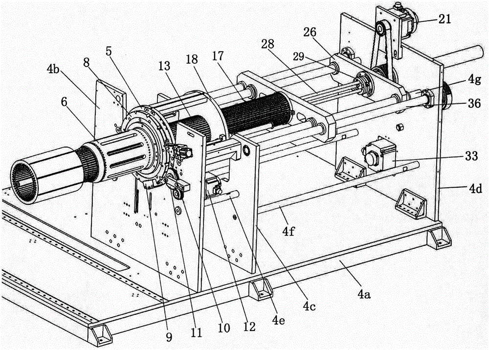
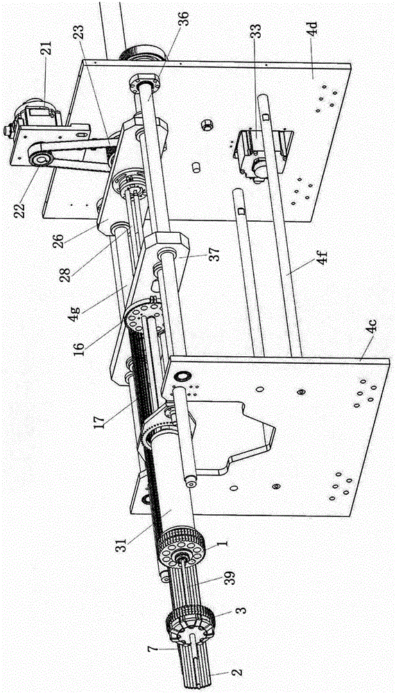
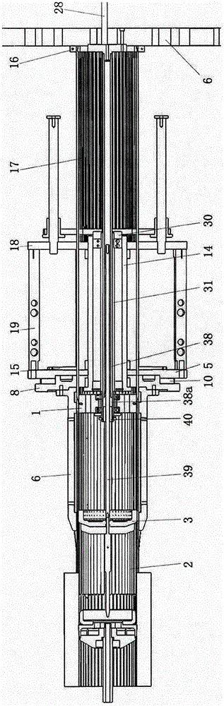
[0028] Such as Figure 1 to Figure 6 As shown, the stator wire embedding device of the present invention includes a guide bar mounting seat 1, several guide bars 2, a push head 3, a bracket 4, a first push rod mechanism, a mounting base, an insulating paper storage device, and a forming insulating paper storage device , the paper pushing mechanism, the first driving mechanism, and the second driving mechanism. The following describes each part and the relationship between them in detail:

[0029] One end of each guide bar is evenly spaced and fixed on the peripheral surface of the guide bar mounting seat to form a non-closed annular space. In this embodiment, the peripheral surface of the guide bar mounting seat 1 is provided with mounting grooves at intervals, and each One end of the guide bar 2 is located in the installation groove and is fixed with the guide bar mounting seat to form a non-closed annular space, and the push head 3 is located in the non-closed annular space....


PUM


Abstract

The present invention discloses a stator wire embedding mold. The stator wire embedding mold comprises a guide bar mounting seat, a plurality of guide bars and a push head; one end of each guide bar is evenly distributed at intervals and fixed on the peripheral surface of the guide bar mounting seat to form a non-closed ring-shaped space; the push head is located in the non-closed ring-shaped space; the stator wire embedding mold further comprises a connecting pipe, a mounting base, an insulating paper storage device and a paper push mechanism; one end of the push head is connected with one end of the guide bar mounting seat through the connecting pipe; one end of the insulating paper storage device is mounted at one end of the mounting base; the insulating paper storage device surrounds the guide bars; an interval into which the paper push mechanism can be inserted is arranged on the peripheral surface of the insulating paper storage device, wherein the interval is distributed along the axial direction of the insulating paper storage device; through holes through which insulating paper goes through are formed in the axial end surfaces of the mounting base and the insulating paper storage device; and the paper push mechanism is located at one end of the mounting base, wherein the one end of the mounting base is opposite to the end of the mounting base which is provided with the insulating paper storage device. With the stator wire embedding mold of the invention adopted, relative movement between the guide bars and enameled wires can be avoided in a stator wire embedding process.

Description

technical field [0001] The invention relates to the technical field of motors, in particular to a stator wire embedding mold and a stator wire embedding device. Background technique [0002] The stator is an important part of the motor. There are many occasions where the motor is used in industrial products. Many electrical products are used as the driving power source. The stator is the main part of the motor. The stator is mainly composed of coils and iron cores. The traditional stator processing process is mostly the The copper wire is wound on the wire mold, and then the copper coil is manually embedded into the stator core. This processing method has many disadvantages: low efficiency; high requirements for manual skills, and the artificial embedded wire is relatively loose, which affects the stator core. performance. [0003] With the advancement of science and technology, the production method of the stator has also changed, that is, the coil is embedded into the sta...

Claims


Application Information

Patent Timeline
IPC IPC(8): H02K15/085H02K15/10
CPCH02K15/085H02K15/10
Inventor 钟仁康成冰仇永杰
Owner CHANGZHOU JINKANG PRECISION MECHANISM
Why Eureka
Try Eureka