False boss for part numerical control machining

A technology of processing technology and bosses, which is applied in the field of CNC machining technology bosses of parts, can solve the problems of insufficient pressing force, increase of process and cost, and rotation of bosses, etc., to reduce displacement and rotation, and prevent bosses from being crushed Or the effect of scratching parts and increasing the radius of action

Inactive Publication Date: 2019-04-12
CHENGDU AIRCRAFT INDUSTRY GROUP
View PDF5 Cites 3 Cited by
  • Summary
  • Abstract
  • Description
  • Claims
  • Application Information

AI Technical Summary

Problems solved by technology

The method of adding pins requires additional processes and costs. In addition, the displacement of the boss can be reduced to a certain extent by adding a compression washer. However, if the installation is not in place and the deviation between the center of the nut and the center of the screw is too large, it will still cause compression. Insufficient force, the problem of boss rotation occurs

Method used


Image

  • False boss for part numerical control machining
  • False boss for part numerical control machining
  • False boss for part numerical control machining

Examples


Embodiment 1

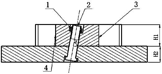
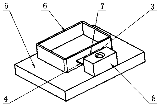
[0025] The present invention is realized through the following technical solutions, such as Figure 1-Figure 3 As shown, a part numerical control machining process boss is connected with part 6, including a boss 8 installed on tooling 5, a connecting edge 7 installed on boss 8 and arranged parallel to the side of tool 5 close to boss 8 And a compression bolt used to fix the boss 8 and the tooling 5; the boss 8 is provided with a compression screw hole, the tool 5 is provided with a stepped through hole communicating with the compression screw hole, the compression The tightening screw holes are sequentially stepped through holes and compression screw holes; the midline of the compression screw hole in the longitudinal direction forms an included angle α with the plane of the tool 5 on the side close to the boss 8, and the included angle α is less than 90 degrees, The longitudinal centerline of the stepped through hole is on the same straight line as the longitudinal centerline ...

Embodiment 2

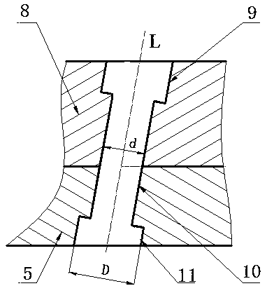
[0029] This embodiment is further optimized on the basis of the above embodiment as figure 1 As shown, further, in order to better implement the present invention, the compression screw hole includes a small hole having the same diameter as the small end of the stepped through hole and communicating with the small end of the stepped through hole, and a large hole 9 connected to the end of the small hole away from the stepped through hole. ; The aperture of the small holes is smaller than the aperture of the large holes.

[0030] The stepped through hole includes a small hole A connected to the small hole, and a large hole A 11 arranged at one end of the small hole A away from the small hole. The hole diameter of the small hole A is the same as that of the small hole. The hole diameter is the same as that of the large hole 9. The A small hole and the small hole form a screw hole for installing a compression screw rod.

[0031] The other parts of this embodiment are the same as the ...

Embodiment 3

[0033] This embodiment is further optimized on the basis of the above embodiment, such as figure 1 As shown, further, in order to better implement the present invention, the height of the boss 8 is H1, and the height of the tooling 5 is H2, that is, the length of the tooling 5 along the longitudinal axis of the compression screw is H2, The length of the boss along the longitudinal axis of the compression screw is H1; the length of the screw 2 in the compression screw is L, L<(H1+H2) / sinα.

[0034] It should be noted that through the above improvement, the compression screw includes: nut 1 and screw 2, the compression screw is of standard shape, the length of the screw is L, and L should satisfy: L<(H1+H2) / sinα;

[0035] Preferably, L should satisfy: L<(H1+H2)*sinα;

[0036] The diameter of the compression screw is standard specifications: 12mm, 16mm, 25mm, and the length of the threaded area should ensure that there are threads within the height of the nut 1;

[0037] The other parts ...


PUM


Abstract

The invention discloses a false boss for part numerical control machining. The boss is connected with a part and comprises a boss body, a connecting edge and a pressing bolt, wherein the boss body isarranged on a tool, the connecting edge is arranged on the boss body and is parallel to the side, close to the boss body, of the tool, and the pressing bolt is used for fixing the boss body and the tool; a pressing screw hole is formed in the boss body, and a step through hole communicating with the pressing screw hole is formed in the tool; the pressing bolt sequentially penetrates through the step through hole and the pressing screw hole; an included angle alpha is formed between the center line of the pressing screw hole in the length direction and a plane on the side, close to the boss body, of the tool, the included angle alpha is smaller than 90 degrees, and the center line of the step through hole in the length direction and the center line of the pressing screw hole in the length direction are located on the same straight line; and a large end of the step through hole is away from the boss body. According to the false boss, part damage caused by rotation and displacement of thefalse boss can be effectively prevented.

Description

Technical field [0001] The invention relates to the technical field of mechanical processing, in particular to a part numerical control processing technology boss. Background technique [0002] With the continuous optimization and improvement of modern design methods and processing methods, various parts are gradually developing in the direction of large-scale, complex, and integrated, and the processing cycle is increasingly shortened, and the requirements for processing quality are gradually increasing. In order to improve the processing efficiency of parts, at this stage, aluminum, titanium alloy, and stainless steel parts are mostly processed by CNC machining, and process bosses are added to the parts to fix and align the parts. With the gradual increase in the number of process bosses of parts, in order to improve the processing efficiency of parts, it is usually required to remove most of the process bosses during the CNC machining process. [0003] The process boss is conne...

Claims


Application Information

Patent Timeline
Patent Type & Authority Applications(China)
IPC IPC(8): B23Q3/06
CPCB23Q3/06
Inventor 黄方林胡颖晓罗广权王绍江
Owner CHENGDU AIRCRAFT INDUSTRY GROUP
Why Eureka
Try Eureka