Channel for conveying bill or paper

A paper feeding channel and channel technology, applied in the field of conveying bills or paper channels, can solve the problems of prone to errors, high labor intensity, traditional bill paper conveying process, etc., and achieve the effect of reducing design size and facilitating recycling and processing.

Pending Publication Date: 2018-12-25
BEIJING C&W ELECTRONICS GRP
View PDF0 Cites 3 Cited by
  • Summary
  • Abstract
  • Description
  • Claims
  • Application Information

AI Technical Summary

Problems solved by technology

At present, the reimbursement process of existing bills is very complicated, which is mainly reflected in the fact that the transfer process of bill paper is very traditional. It cannot automatically classify and

Method used


Image

  • Channel for conveying bill or paper
  • Channel for conveying bill or paper
  • Channel for conveying bill or paper

Examples


Embodiment 1

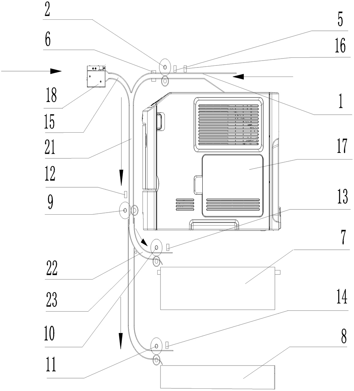
[0033] Example 1, such as figure 1 As shown, a passage for conveying bills or papers includes a horizontally arranged printing paper passage 1, a scanning paper passage 15, a connecting passage 21, a storage box A paper feed passage 22 and a storage box B paper feed passage 23. One end of the printing paper-feeding channel 1 and the scanning paper-feeding channel 15 communicate with the top end of the vertically established connecting channel 21, and the end of the printing paper-feeding channel 1 away from the connecting channel 21 communicates with the printer 17, The end of the scanning paper passage 15 away from the connecting passage 21 is connected to the scanner 18; the paper printed by the printer 17 enters the connecting pipe 21 through the printing paper passage 1, and the bills scanned by the scanner 18 pass through the scanning The paper path 15 enters into the connecting pipe 21 .

[0034] The bottom end of the connecting passage 21 communicates with the paper fe...

Embodiment 2

[0036] Embodiment 2, according to Figure 4 As shown, the difference between this embodiment and Embodiment 1 is that the printing paper feeding channel 22 is arranged obliquely to match the paper output of the printer 17 , which reduces the resistance of paper output.

Embodiment 3

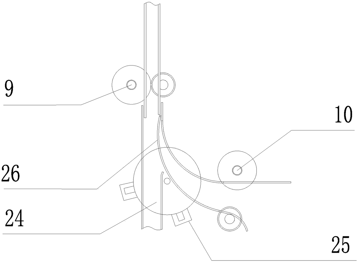
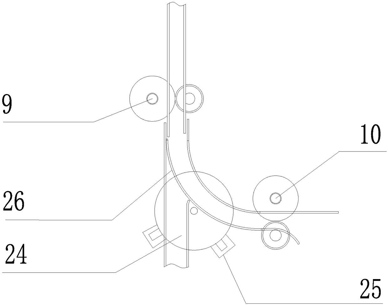
[0037] Embodiment 3, according to figure 2 As shown, the difference between this embodiment and Embodiment 1 is that the paper-pushing mechanism includes a cardboard code wheel 24, an infrared detection switch 25, and a cardboard 26, and the outer wall of the paper feeding channel 23 of the storage box B is hinged with a cardboard code Disk 24, the cardboard 26 runs through the cardboard code disc 24, one end of the cardboard 26 is connected to the side of the storage box A paper feed channel 22 close to the storage box B paper feed channel 23, the The infrared detection switch 25 is arranged on the outside of the cardboard code wheel 24 for controlling the cardboard code wheel 24 to drive the cardboard 26 to move. When the paper or bill passes through the paper-pushing mechanism, the end of the paper-pushing plate 26 close to the paper guide wheel B9 closes the paper feeding channel 22 of the storage box A, and the paper or bill enters the paper feeding channel 23 of the sto...


PUM


Abstract

The invention relates to a channel for conveying a bill or paper. The channel comprises a printing paper feeding channel, a scanning paper feeding channel, a connecting channel, a storage box A paperfeeding channel and a storage box B paper feeding channel; one end of each of the printing paper feeding channel and the scanning paper feeding channel is communicated with the top end of the connecting channel which is arranged vertically; one end, far away from the connecting channel, of the printing paper feeding channel is communicated with a printer; one end, far away from the connecting channel, of the scanning paper feeding channel is communicated with a scanner; and after the paper or bill enters the connecting channel, the paper or bill enters the storage box A paper feeding channel or the storage box B paper feeding channel correspondingly according to the set classification and under the action of a paper prodding mechanism, so that the paper or bill is collected in the storagebox A and the storage box B correspondingly. The channel for conveying the bill or paper avoids high-intensity work of manual classification, effectively improves the working efficiency and has greatmarket prospect.

Description

technical field [0001] The invention relates to the field of bill self-service processing mechanical equipment, in particular to a channel for conveying bills or paper. Background technique [0002] As employees of enterprises, institutions, financial companies, and corporate companies need to reimburse more and more bills, the workload of financial personnel is increasing, and the time for processing bills is getting longer and longer. At present, the reimbursement process of existing bills is very complicated, which is mainly reflected in the fact that the transfer process of bill paper is very traditional. It cannot automatically classify and convey different types of bills. Manual classification is not only labor-intensive but also prone to errors, slowing down The efficiency of bill reimbursement and sorting has affected the work efficiency of the unit. Contents of the invention [0003] The technical problem to be solved by the present invention is to provide a chan...

Claims


Application Information

Patent Timeline
IPC IPC(8): B41J3/44B41J3/407B41J13/10B41J11/00
CPCB41J3/4075B41J3/445B41J11/0095B41J13/10
Inventor 陶军强张成
Owner BEIJING C&W ELECTRONICS GRP
Why Eureka
Try Eureka