Collimating microlens array

a collimating film and microlens technology, applied in the field of collimating microlens arrays, can solve the problems of difficult manufacturing of microlens collimating films, inability to tailor or modify the shape of emission envelopes to suit the desired shape of the intended backlight application, and small apertures, etc., to achieve high output luminance, easy manufacturing, and high lumen efficiency

Inactive Publication Date: 2007-01-04
ORAFOL AMERICAS
View PDF16 Cites 84 Cited by
  • Summary
  • Abstract
  • Description
  • Claims
  • Application Information

AI Technical Summary

Benefits of technology

[0008] Therefore, among the objects of the present invention are to provide a collimating film having high output luminance, whose output collimating envelope can b...

Problems solved by technology

However, this prism-based collimating film has two significant drawbacks.
Secondly, the shape of the emission envelope can not be tailored or modified to suit the desired shape for the intended backlight application.
However, for all its benefits, the microlens-based collimating film has proven to be difficult to manufacture.
It has been found that producing an aperture that is a few microns in diameter in a reflective layer is problematic...

Method used


Image

  • Collimating microlens array
  • Collimating microlens array
  • Collimating microlens array

Examples


Embodiment Construction

[0045] A description of preferred embodiments of the invention follows.

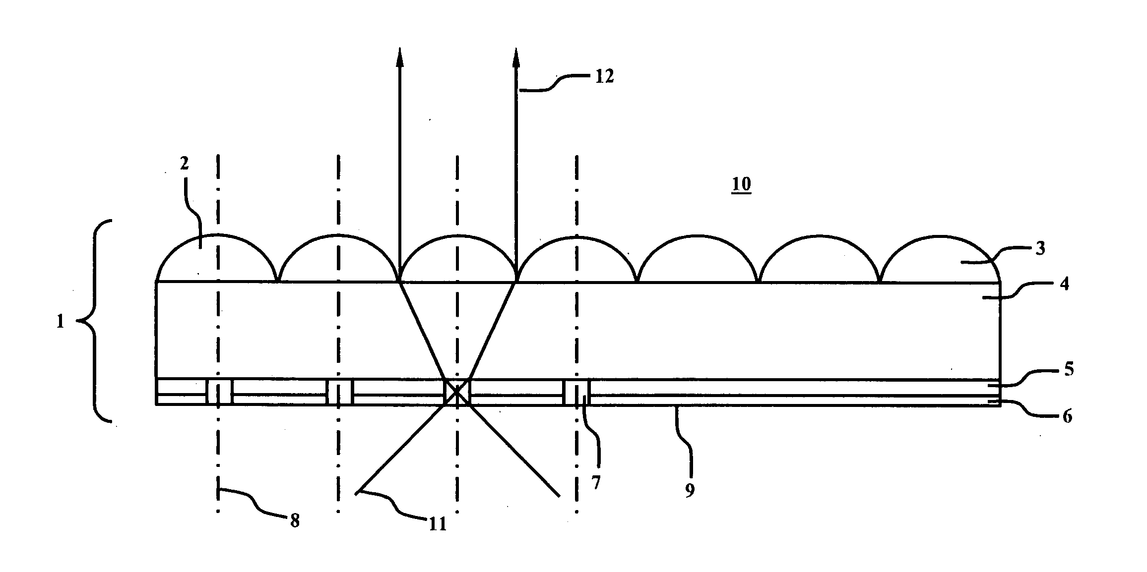
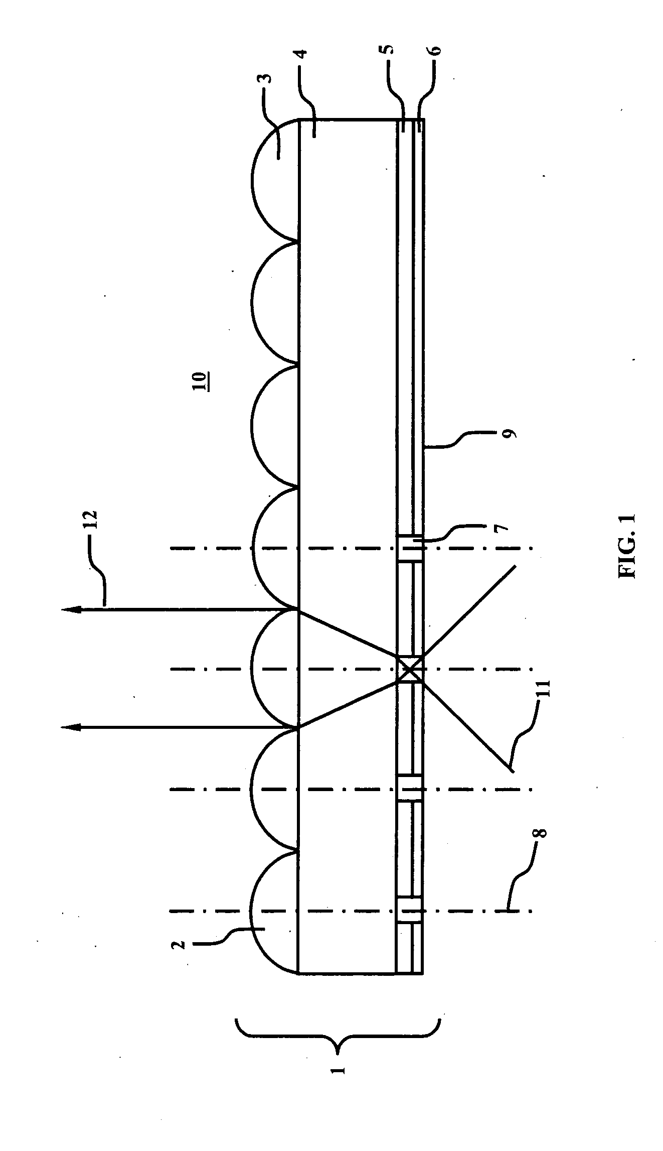
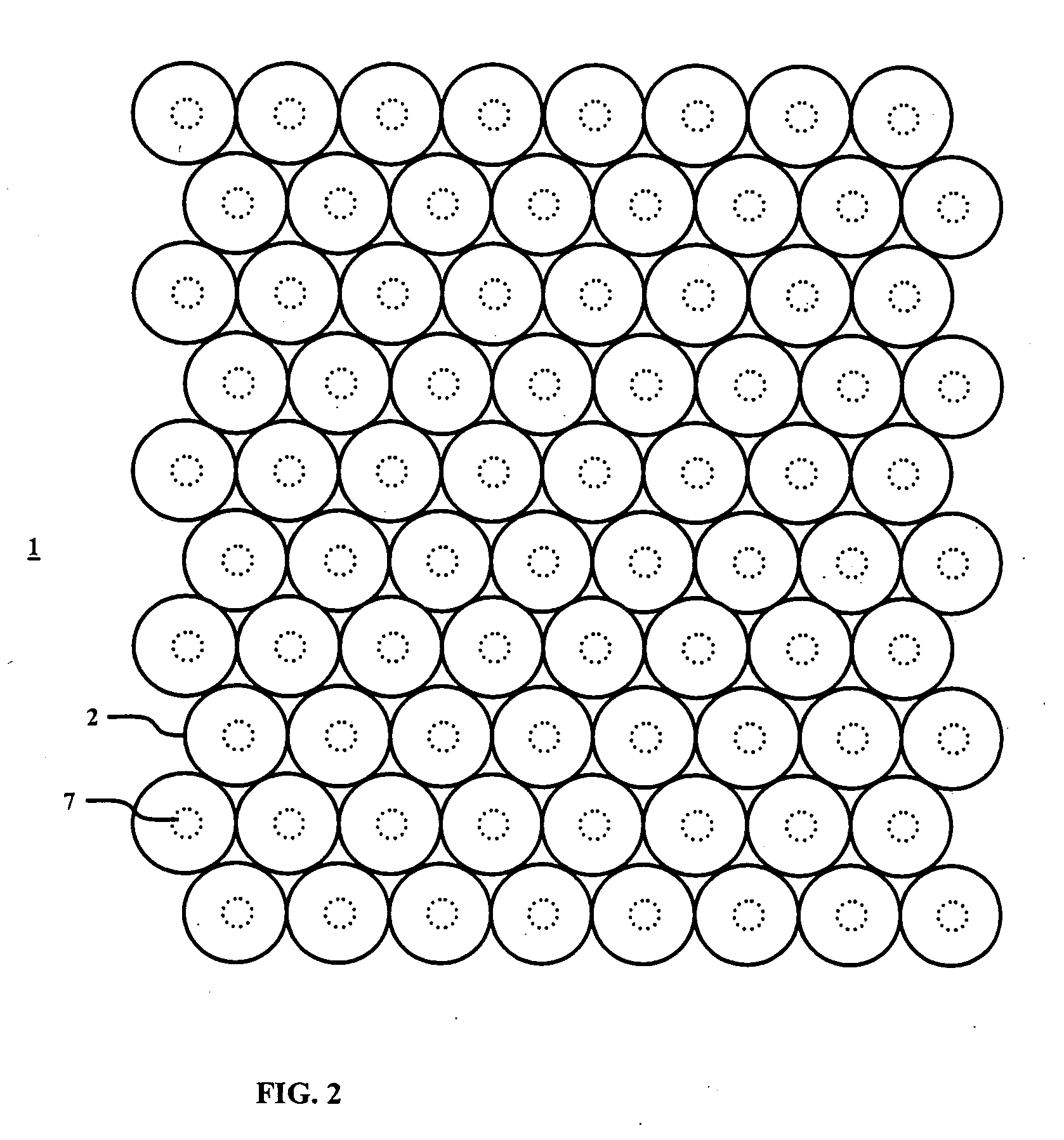
[0046] In one embodiment, the present invention includes a film with a substrate, a lens array on the output side of the film, and a specularly reflective layer—with apertures at or near the focal positions of the lenslets of the lens array—installed on the input side of the film. Additionally, a light absorbing layer—with similar apertures—can be installed between the substrate and the reflective layer to facilitate aperture formation and stray light absorption. Furthermore, the specularly reflective layer may include layers of dielectric and / or layered metallic materials.

[0047] Other embodiments of the invention are directed to methods of making such films. The specific methods involve the use of a laser to ablate apertures in the collimating film.

[0048] Referring to FIG. 1, the collimating film 1 is shown to be made from a substrate 4, a lens array 3 comprised of a plurality of individual lenslets 2, an opt...


PUM


Abstract

A collimating sheet, for use with a backlit display and the like, that includes a substrate, a plurality of microlenses on the output side of the substrate, a specularly reflective layer on the side of the substrate opposite the microlenses, and a plurality of apertures in the reflective layer in direct correspondence to the microlenses of the lens array. The specularly reflective layer can be relatively thinner than a diffuse reflective layer, which allows light to pass through the more readily. One or more layers of dielectric can be placed on top of one or more reflective material layers to further improves overall reflectivity. Apertures are preferably made in the light-absorptive and reflective layers with a laser ablation process wherein laser light illuminates the output side of the film. The laser light is brought to a focus by the lenslets of the lens array onto the light-absorptive layer, which then ablates a hole or aperture into the light-absorptive and reflective layer. In this way, the apertures are self-aligned with the lenslets.

Description

RELATED APPLICATION [0001] This application claims the benefit of U.S. Provisional Application No. 60 / 694,838, filed Jun. 29, 2005. The entire teachings of the above application(s) are incorporated herein by reference.BACKGROUND OF THE INVENTION [0002] Flat panel displays are now generally preferred over cathode ray tubes in a wide variety of applications, ranging from desktop and laptop computers to television screens. The perceived quality of an image reproduced by, say, a Liquid Crystal Display (LCD) depends greatly on its ability to provide high brightness and contrast. Such displays commonly use a backlight arrangement, where a light-diffusing plate is placed between a light source and the liquid crystal panel. It is also common for one or more collimating film sheets to be placed on or near the light diffusing plate. The collimating films serve the purpose of increasing the brightness of the display, a most desirable characteristic. [0003] One type of collimating film incorpor...

Claims


Application Information

Patent Timeline
IPC IPC(8): G02B27/10
CPCB29D11/00278G02B3/0025G02B3/0056G02B6/0053G09G3/3406G02B27/30G02F1/133605G02F2001/133607G03B21/625G02B27/0961G02F1/133607
Inventor MUNRO, JAMES F.
Owner ORAFOL AMERICAS
Why Eureka
Try Eureka