Light source device and image display device

A light source device and light beam technology, which is applied in the field of light sources, can solve the problems of affecting the service life of image display devices, reducing the transmittance and service life of optical elements, and the output brightness cannot meet the brightness requirements, etc.

Active Publication Date: 2016-03-30
QINGDAO HISENSE LASER DISPLAY CO LTD
View PDF6 Cites 4 Cited by
  • Summary
  • Abstract
  • Description
  • Claims
  • Application Information

AI Technical Summary

Problems solved by technology

As image display devices are widely used in scenes such as cinemas, the demand for output brightness of image display devices has increased, and the output brightness (about 3000 lumens) of current image display devices cannot meet the brightness requirements; therefore, how to improve image display The output brightness of the light source of the device is a technical problem that needs to be solved urgently
[0003] In the prior art, the output brightn

Method used


Image

  • Light source device and image display device
  • Light source device and image display device
  • Light source device and image display device

Examples


Embodiment 1

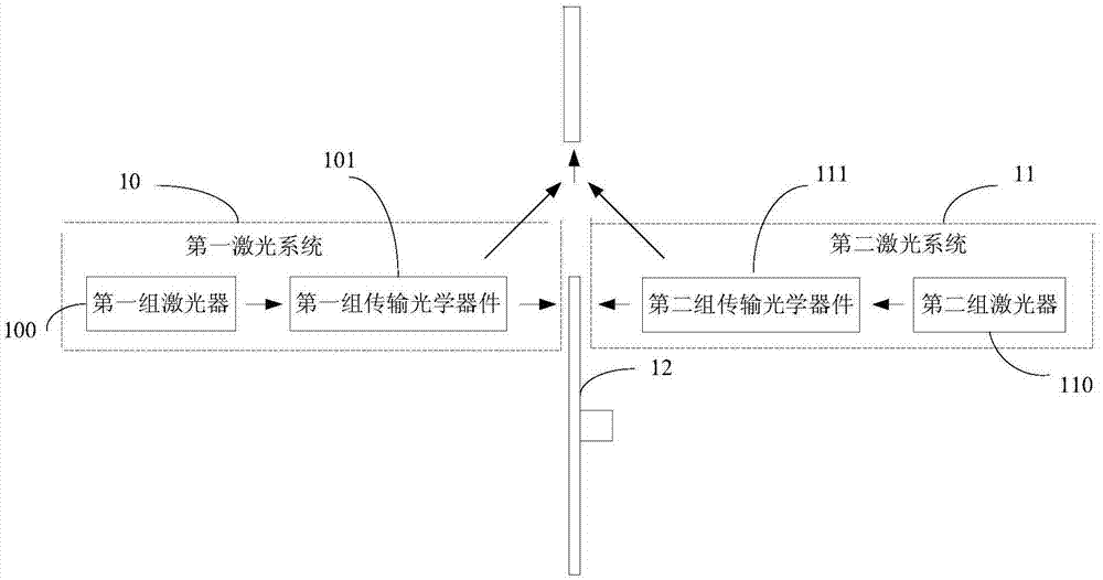
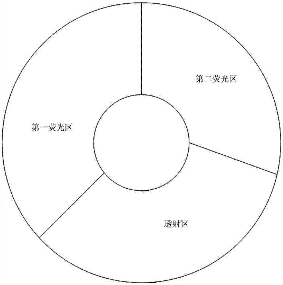
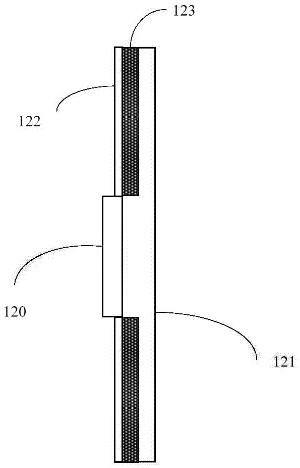
[0021] Figure 1A It is a schematic structural diagram of Embodiment 1 of the light source device of the present invention, such as Figure 1A As shown, the light source device includes: a first laser system 10, a second laser system 11, and a fluorescent wheel 12; the first laser system 10 includes: a first group of lasers 100 and a first group of transmission optical components 101; the second The laser system 11 includes: a second group of lasers 110 and a second group of transmission optical components 111 (optionally, each group of lasers may include: at least two lasers); the fluorescent wheel 12 includes: a fluorescent area and a transmission area (optional Alternatively, the fluorescent wheel is a transmissive fluorescent wheel; the fluorescent wheel is rotated by a motor arranged in the center); optionally, the surface of the fluorescent wheel area facing the first laser system 10 is provided with a A polarized light beam and a second polarized light beam are provided,...

Embodiment 2

[0030] Figure 2A It is a schematic structural diagram of Embodiment 2 of the light source device of the present invention. On the basis of the above embodiments, the first group of transmission optical components 101 includes: a first light-combining lens 101a; the second group of transmission optical components 111 includes: Two light-combining lenses 111a; wherein, a film for transmitting the first polarized light beam and reflecting the second polarized light beam is provided on the first surface of the first light-combining lens 101a close to the first group of lasers 100 A film layer for transmitting the first polarized light beam is provided on the second surface of the first light combining lens 101a close to the fluorescent wheel 12; in the second light combining lens 111a close to the second A film layer for transmitting the second polarized light beam and reflecting the first polarized light beam is provided on the third surface of the group laser 110, and the fourt...

Embodiment 3

[0035] Figure 2C It is a schematic structural diagram of the third embodiment of the light source device of the present invention, in the above Figure 2A and Figure 2BOn the basis of the above, the first set of transmission optical components 101 also includes: a first collimating lens group 101c, wherein the first collimating lens group 101c is arranged between the first light-combining lens 101a and the fluorescent wheel between 12; the first collimating lens group 101c is used to: collimate the first polarized light beam passing through the first light-combining lens 101a, and direct it to the fluorescent wheel 12; The second polarized light beam of the fluorescent wheel 12 is collimated and directed to the first light-combining lens 101a; and / or, the second group of transmission optical components 111 further includes: a second collimating lens group 111c, wherein, The second collimating lens group 111c is disposed between the second light combining lens 111a and the ...


PUM


Abstract

The embodiment of the invention provides a light source device and an image display device. The light source device comprises a first laser system, a second laser system and a fluorescent wheel, wherein the first laser system comprises a first group of laser devices and a first group of transmitting optical components; the second laser system comprises a second group of laser devices and a second group of transmitting optical components; the fluorescent wheel comprises a fluorescent region and a transmission region; first polarized beams generated by the first group of laser devices and second polarized beams generated by the second group of laser devices irradiate two opposite surfaces of the same region of the fluorescent wheel respectively; obviously, the transmitting optical components corresponding to each laser system simultaneously output beams respectively; and two beams are superposed to obtain a high-brightness hybrid white light, so that the output brightness of the light source device and the image display device is improved.

Description

technical field [0001] Embodiments of the present invention relate to light source technology, and in particular, to a light source device and an image display device. Background technique [0002] Usually, in image display devices (such as projectors), laser light generated by a group of lasers is mostly used as the light source of the image display device. The image generation part of the device is used to form the image to be displayed; generally, the output brightness of the light source of the image display device is about 6000-10000 lumens, and the corresponding output brightness of the image display device is about 3000 lumens. As image display devices are widely used in scenes such as cinemas, the demand for output brightness of image display devices has increased, and the output brightness (about 3000 lumens) of current image display devices cannot meet the brightness requirements; therefore, how to improve image display The output brightness of the light source of...

Claims


Application Information

Patent Timeline
IPC IPC(8): G03B21/20
CPCG03B21/2013G03B21/204G03B21/2073G03B21/208
Inventor 李巍刘显荣田有良
Owner QINGDAO HISENSE LASER DISPLAY CO LTD
Why Eureka
Try Eureka