Intelligent drawer type reactive compensation device with compensation function and special shipping car

A compensation device, a drawer-type technology, applied in reactive power compensation, reactive power adjustment/elimination/compensation, switchgear, etc., can solve problems such as maintenance difficulties, stable power factor, power system cannot be guaranteed, etc., to achieve high power factor Effect

Inactive Publication Date: 2011-04-06
HARBIN INST OF TECH
View PDF3 Cites 6 Cited by
  • Summary
  • Abstract
  • Description
  • Claims
  • Application Information

AI Technical Summary

Problems solved by technology

[0002] If a component in the existing reactive power compensation device fails, all the components need to be shut down; when the load is light, the system will oscillate; the service life of capacitors and reactors is short; harmonic currents easily invade the reactive power compensation device and burn out components; and The existing reactive power compensation devices are all in the form of an integral structure, which is difficult to maintain; the structure cannot be uniformly finalized; the product quality is difficult to control; it cannot meet the development requirements of users, and the flexibility is poor. When one of the devices fails, the entire device must be completely Quit working, so that the reactive power compensation device cannot play the role of reducing loss and saving energy, and the power system cannot guarantee a relatively stable power factor
Moreover, the existing reactive power compensation device is prone to system oscillation when the load is light, the service life of capacitors and reactors is short, and the harmonic current will invade the reactive power compensation device and burn out components
Moreover, the prior art does not provide a kind of auxiliary equipment specially used to realize the assembly or disassembly of the compensating device.

Method used


Image

  • Intelligent drawer type reactive compensation device with compensation function and special shipping car
  • Intelligent drawer type reactive compensation device with compensation function and special shipping car
  • Intelligent drawer type reactive compensation device with compensation function and special shipping car

Examples


specific Embodiment approach 1

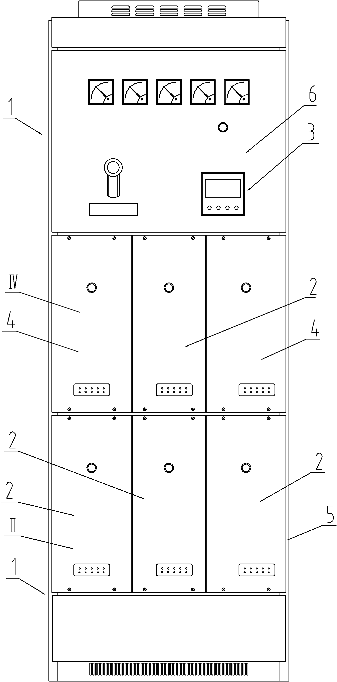
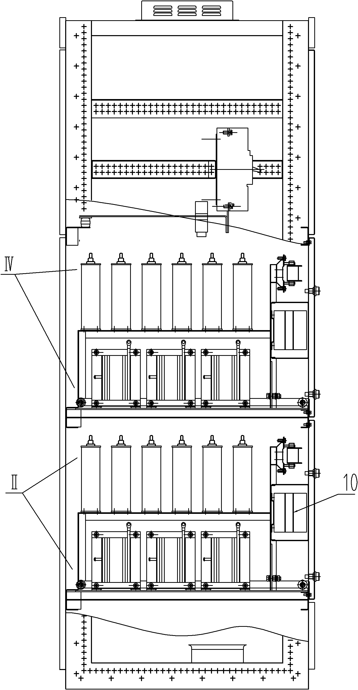
[0011] Specific implementation mode one: as Figure 1-13 As shown, the intelligent drawer-type reactive power compensation device with the compensation function described in this embodiment includes a compensation cabinet 1, a controller 3, a plurality of main compensation single-group compensator units II, and multiple compensation single-group compensator units IV, the reactive power compensation device also includes multiple main compensation single-group compensation drawer housings 2, multiple compensation single-group compensation drawer housings 4, and the multiple main compensation single-group compensation drawer housings 2 and multiple compensation The single-group compensating drawer housings 4 are all orderly and drawably installed at the corresponding positions in the compensating cabinet body 1, and corresponding drawer tracks are arranged in the compensating cabinet body 1, and the multiple main compensating single-group compensating drawer housings Body 2, mult...

specific Embodiment approach 2

[0015] Specific implementation mode two: as Figure 1~6 As shown, the main compensation single-group compensation drawer housing 2 and the compensation single-group compensation drawer housing 4 in this embodiment both include a drawer panel 8, a drawer pull-out booster mechanism 9, a drawer frame 13 and a travel pulley 16. The drawer panel 8 is installed on the front end of the drawer frame 13 , the travel pulley 16 is arranged on the bottom of the drawer frame 13 , and the drawer pull-out booster mechanism 9 is arranged on the bottom end of the drawer frame 13 and is close to the drawer panel 8 . Wherein the bottom beam rear end of drawer frame 13 protrudes from the frame rear column 5 millimeters, and this protruding part is specially used for inserting the gap between the receiving beam and the track rear beam, and the drawer can be pulled out and advanced easily on the drawer track. Other components and connections are the same as those in the first embodiment.

[0016] ...

specific Embodiment approach 3

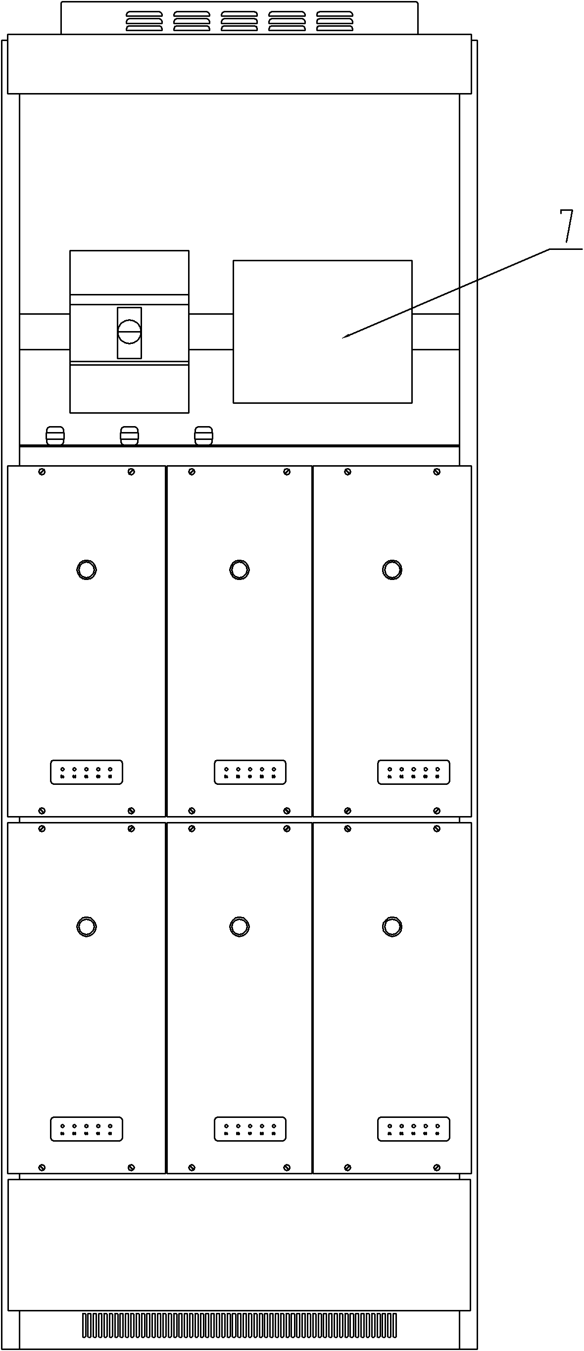
[0017] Specific implementation mode three: as Figure 1-12As shown, the compensation cabinet 1 in this embodiment includes a cabinet frame main body 5, a single set of drawer rails 31, a receiving rail 32, a front beam 33 of a track, and a rear beam 34 of a track. , the front crossbeam 33 of the track and the rear crossbeam 34 of the track are all installed in the cabinet frame main body 5, the front crossbeam 33 of the track is placed on the front end of the single group of drawer tracks 31, and the rear crossbeam 34 of the track is placed at the rear end of the single group of drawer tracks 31. The rear end of the group drawer track 31 is designed with a slope of 15 degrees to connect with the receiving track 32, and there is a gap (5 mm) between the upper side of the receiving track 32 and the inner side of the upper side of the track rear crossbeam 34 for the protruding part of the drawer frame 13 to be inserted and locked. for. Other compositions and connections are the ...


PUM


Abstract

The invention relates to an intelligent drawer type reactive compensation device with compensation function and a special shipping car thereof, belonging to the field of power reactive compensation, capable of realizing independent protection and control of each compensation unit group and conveniently pushing main compensation single compensation drawer and a compensation single compensation drawer into a compensation cabinet or drawing the main compensation single compensation drawer and compensation single compensation drawer out from the compensation cabinet for maintenance. The invention has the key points that: multiple main compensation single compensation drawer cases and multiple compensation single compensation drawer cases are all sequentially arranged at corresponding positions in the compensation cabinet in a drawable way, and multiple main compensation single compensation drawer cases and multiple compensation single compensation cases can be conveniently drawn out from the compensation cabinet or pushed to the corresponding positions in the compensation cabinet by virtue of the drawer rail. A movable rail frame is arranged on a shipping frame by virtue of a rail suspension mechanism, the movable rail frame can slide up and down along the shipping frame, and a rail frame height regulating mechanism is arranged below the movable rail frame. The invention is applicable to distribution automation implementation and modification of various power grids.

Description

technical field [0001] The invention relates to a reactive power compensation device and a special delivery vehicle, in particular to an intelligent drawer-type reactive power compensation device with a compensation function and a delivery vehicle for assembling the compensation device, belonging to the field of electric reactive power compensation. Background technique [0002] If a component in the existing reactive power compensation device fails, all the components need to be shut down; when the load is light, the system will oscillate; the service life of capacitors and reactors is short; harmonic currents easily invade the reactive power compensation device and burn out components; and The existing reactive power compensation devices are all in the form of an integral structure, which is difficult to maintain; the structure cannot be uniformly finalized; the product quality is difficult to control; it cannot meet the development requirements of users, and the flexibilit...

Claims


Application Information

Patent Timeline
Patent Type & Authority Applications(China)
IPC IPC(8): H02J3/18H02B11/173
CPCY02E40/30
Inventor 唐文彦徐春华张晓琳王军马强
Owner HARBIN INST OF TECH
Why Eureka
Try Eureka