Clamping-nail fixing structure for lamp cap

A fixed structure and staple technology, which is applied to discharge lamps, discharge tubes, electrical components, etc., can solve problems such as potential safety hazards, complicated processes, and poor spot welding

Inactive Publication Date: 2012-12-05
DONGGUAN CASUN LAMPBASE IND CO LTD
View PDF0 Cites 0 Cited by
  • Summary
  • Abstract
  • Description
  • Claims
  • Application Information

AI Technical Summary

Problems solved by technology

[0003] 1. Using high frequency or air cylinder to drive into the insulation part, the process is complicated, the cost is high, and the processing size is difficult to control, so there are many defective products
[0004] 2. First process two clips separately, for example, a cylindrical clip, and then spot weld the clips on the metal shell of the lamp head respectively. Using this fixing method, poor spot welding may occur, resulting in clips And damage to the metal shell, especially, during use, the welding part may become loose or even fall off, which will affect the performance of the entire energy-saving lamp, and there are potential safety hazards that may cause harm to people
[0005] 3. First process two staples separately, for example, a cone-shaped staple, insert the smaller end of the staple from the outside of the metal shell into the inside of the metal shell, and fix it through the insulating part. This kind of fixing structure is relatively relatively Stable, but in the process of embedding the staples on the shell wall of the metal shell by external force, it is very easy to produce defective products, and this process will deform the metal shell and reduce the quality of the product

Method used


Image

  • Clamping-nail fixing structure for lamp cap
  • Clamping-nail fixing structure for lamp cap
  • Clamping-nail fixing structure for lamp cap

Examples


Embodiment Construction

[0042] The present invention will be further described below in conjunction with the accompanying drawings and specific embodiments.

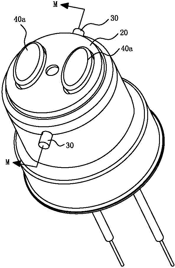
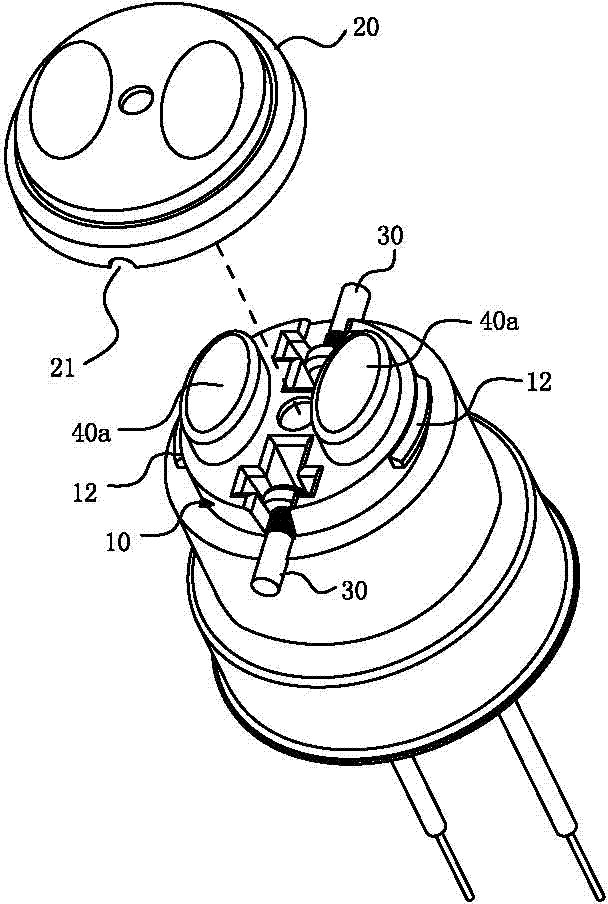
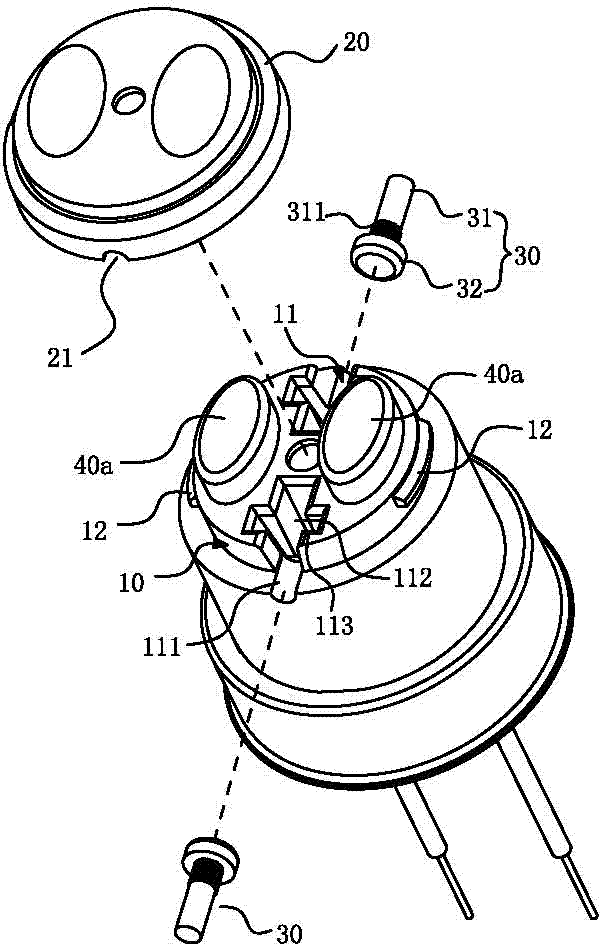
[0043] See Figure 1 to Figure 5 As shown, it shows the specific structure of the first embodiment of the present invention, including a fixed joint case 10 , an insulating cover 20 and a staple 30 .

[0044] Wherein, the number of the staples 30 is two, and each staple 30 includes a clamping part 31 and a limiting part 32 integrally connected, and a plurality of clamping parts are arranged on the outer surface of the clamping part 31 near the limiting part 32. The tooth-shaped convex strip 311, of course, can also be other structural designs such as convex points that can make the surface friction force large enough to prevent the staple 30 from rotating, and is not limited thereto; generally speaking, in this embodiment, , the aforementioned clip 30 is in the shape of a rivet, the aforementioned clamping portion 31 is in the shape of a rivet...


PUM


Abstract

The invention discloses a clamping-nail fixing structure for a lamp cap, which comprises a fixedly-connected head shell, an insulating cover and a clamping nail, wherein the clamping nail comprises a clamping part and a limiting part, the clamping nail is embedded in a fixed slot of the fixedly-connected head shell, the fixed slot comprises a limiting slot and a containing slot which are communicated, and a stopping part is formed between the limiting slot and the containing slot; a pushing part is convexly arranged on the insulating cover, and when the insulating cover is installed on the fixedly-connected head shell, the pushing part is embedded in the limiting slot, the clamping nail is outwards pushed to the limiting part of the clamping nail to be abutted on the stopping part, the clamping part of the clamping nail is exposed outside the fixedly-connected head shell, and the top end of an open slot of the insulating cover is compacted on the clamping part; and thereby, in the invention, the clamping nail only needs to be placed in the fixed slot and the insulating cover is installed by means of no other fixed mechanisms, so that the stable installation for the clamping nail can be realized, the clamping nail is convenient and rapid to assemble, and the clamping nail, the fixedly-connected head shell and the insulating cover have simple structures and are easy to manufacture.

Description

technical field [0001] The invention relates to the technical field of lamp caps, in particular to a staple fixing structure of a lamp cap. Background technique [0002] At present, more and more homes and offices have applied energy-saving lamps. Therefore, it is the general trend for energy-saving lamps to replace ordinary light bulbs. The traditional snap-on energy-saving lamp head includes a shell, an insulating part, a conductive cap and a staple, and the staple is usually fixed by the following methods: [0003] 1. Using high frequency or air cylinder to drive into the insulating part, the process is complicated, the cost is high, and the processing size is difficult to control, so there are many defective products. [0004] 2. First process two clips separately, for example, a cylindrical clip, and then spot weld the clips on the metal shell of the lamp head respectively. Using this fixing method, poor spot welding may occur, resulting in clips And damage to the met...

Claims


Application Information

Patent Timeline
Patent Type & Authority Patents(China)
IPC IPC(8): H01J5/60
Inventor 姚利民
Owner DONGGUAN CASUN LAMPBASE IND CO LTD
Why Eureka
Try Eureka