Artificial ventilation apparatus

A technology of artificial respiration and inspiratory circuit, which is used in respirator and other directions

Inactive Publication Date: 2012-01-04
NIHON KOHDEN CORP
View PDF5 Cites 15 Cited by
  • Summary
  • Abstract
  • Description
  • Claims
  • Application Information

AI Technical Summary

Problems solved by technology

Therefore, this device also has a very troublesome problem in that it is necessary to check that the carbon dioxide concentration detector and the like are surely connected so that poor ventilation of th

Method used


Image

  • Artificial ventilation apparatus
  • Artificial ventilation apparatus
  • Artificial ventilation apparatus

Examples


Embodiment Construction

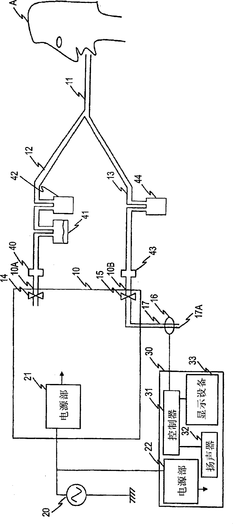
[0031] Hereinafter, various embodiments of the artificial respiration apparatus of the present invention will be described with reference to the accompanying drawings. In the drawings, the same components are denoted by the same reference numerals, and repeated descriptions will be omitted. figure 1 The configuration of the artificial respiration apparatus of the first embodiment is shown. The artificial respiration device comprises a respirator 10 which delivers gas at the required pressure with the oxygen concentration required for artificial respiration.

[0032]The connecting portion 11 connected to the respiratory system of the patient A is joined to the respiratory system. The connecting portion 11 is constituted by a mask, a catheter inserted into the trachea, and the like. The inhalation circuit 12 is connected between the connecting portion 11 and the gas outlet 10A of the respirator 10 , and is a flow path for allowing gas to flow from the respirator 10 to the con...


PUM


Abstract

An artificial ventilation apparatus includes: a connecting portion which is connected to a respiratory system of a patient; an inspiratory circuit which is a flow path for flowing a gas from a ventilator to the connecting portion; an expiratory circuit which is a flow path for guiding a gas exhausted from the connecting portion to an exhaust portion of the ventilator; an expiratory valve which blocks a flow of a gas from the exhaust portion toward the connecting portion; a carbon dioxide concentration sensor which is disposed in a circuit that is arranged at a downstream side of the expiratory valve and which detects a carbon dioxide concentration; and an alarm outputting unit which outputs an alarm based on an output of the carbon dioxide concentration sensor.

Description

technical field [0001] The invention relates to an artificial respiration device including a carbon dioxide concentration sensor. Background technique [0002] The artificial respiration apparatus is equipped with a function of detecting an anaerobic or hypoventilating state of a patient due to a malfunction of a respirator or an abnormality of a breathing circuit and issuing an alarm. In particular, end-tidal CO2 (EtCO2) monitoring can be said to be useful as it can check that the patient is actually performing gas exchange. [0003] EtCO2 measuring mechanisms installed on artificial respiration devices or on patient monitoring devices other than artificial respiration devices such as Figure 4 constructed as shown. [0004] Figure 4 The device shown in is a prior art artificial respiration device and is constructed as follows. The respirator 80 is connected to the respiratory system of the patient A via an inhalation valve 82 as a one-way valve, an infection prevention ...

Claims


Application Information

Patent Timeline
IPC IPC(8): A61M16/00
Inventor 磨田裕小林尚史山森伸二长井靖
Owner NIHON KOHDEN CORP
Why Eureka
Try Eureka