Orthogonal field calibration device for three-component magnetic probe and calibration method thereof

A field calibration, three-component magnetic technology, applied in the direction of geophysical measurement, instruments, etc., can solve the problems of difficult to meet the measurement requirements, unattractive application value, unable to meet the requirements of actual vector measurement, etc., to reduce the measurement cost, The effect of convenient field work and simple structure

Inactive Publication Date: 2012-02-15
JILIN UNIV
View PDF3 Cites 10 Cited by
  • Summary
  • Abstract
  • Description
  • Claims
  • Application Information

AI Technical Summary

Problems solved by technology

The measurement error of the three orthogonal components should be controlled below 1nT, because the accuracy of the total field scalar measurement based on the quantum effect has reached below 0.05nT, and the component accuracy of the vector measurement is above 1nT, and its application value is not very attractive. strong
[0004] At present, the measurement accuracy of the single-component magnetic probe represented by the fluxgate can reach below 1nT, but one of the key problems is that the installation and processing accuracy of the vector measurement of the magnetic field is extremely high for the orthogonal three-component sensor, which is difficult to meet measurement requirements
The orthogonality error of the three-component magnetic probe is difficult to be less than 0.5 degrees
Both theoretical analysis and practice have proved that when converted to the total magnetic field, the error reaches hundreds of nT, which cannot meet the requirements of actual vector measurement at all.
[0005] The calibration of the orthogonality of the three-component sensor can be directly measured with a non-magnetic theodolite in the artificial magnetic field in a large electromagnetic shielding room. Ang non-magnetic theodolite, the general laboratory does not have such conditions

Method used


Image

  • Orthogonal field calibration device for three-component magnetic probe and calibration method thereof
  • Orthogonal field calibration device for three-component magnetic probe and calibration method thereof
  • Orthogonal field calibration device for three-component magnetic probe and calibration method thereof

Examples


Embodiment 1

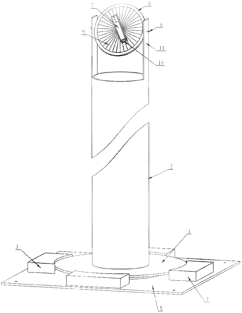
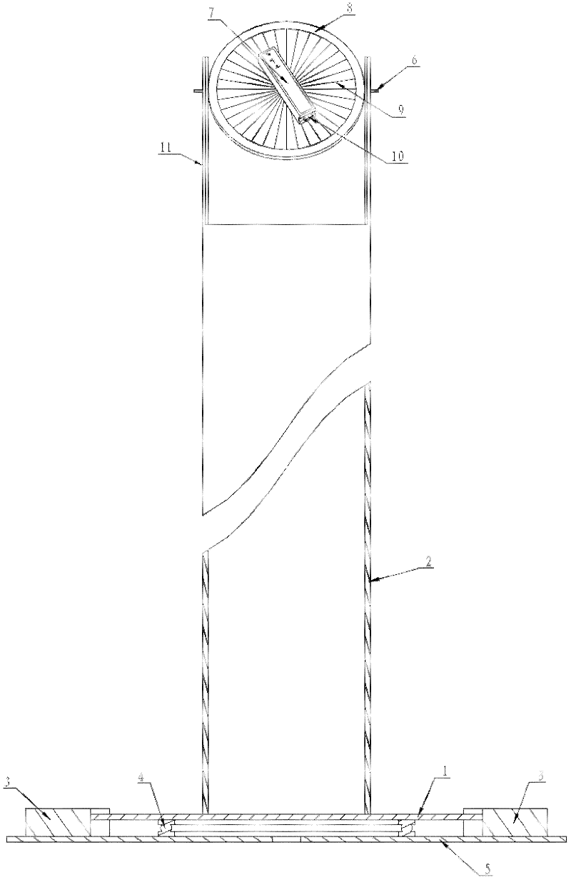
[0043]The field calibration device for the orthogonality of the three-component magnetic probe is composed of a thrust bearing 4 and more than three limit blocks 3 on the base 5, the limit blocks 3 limit the rotation platform 1, and the thrust bearing 4 is equipped with a rotating The platform 1 and the cylinder 2 are fixed on the rotating platform 1. The upper part of the cylinder 2 is an ear-shaped convex strip 11. The diameter of the flat shaft 6 coincides with the diameter of the disc 8 and is fixed on the disc 8. The two ends of the horizontal shaft 6 are respectively Through the two ear-shaped protrusions 11, the disc 8 is suspended between the two ear-shaped protrusions 11, the disc 8 rotates around the horizontal axis 6, the disc 8 is equipped with an angle disc 9, and the three-component probe 7 is passed through a screw or The rotating shaft is fixed on the dial 9, and one end of the three-component probe 7 is equipped with a connector 10 to form it.

[0044] The fie...

Embodiment 2

[0055] The field calibration device for the orthogonality of the three-component magnetic probe is composed of a thrust bearing 4 and more than three limit blocks 3 on the base 5, the limit blocks 3 limit the rotation platform 1, and the thrust bearing 4 is equipped with a rotating The platform 1 and the cylinder 2 are fixed on the rotating platform 1. The upper part of the cylinder 2 is an ear-shaped convex strip 11. The diameter of the flat shaft 6 coincides with the diameter of the disc 8 and is fixed on the disc 8. The two ends of the horizontal shaft 6 are respectively Through the two ear-shaped protrusions 11, the disc 8 is suspended between the two ear-shaped protrusions 11, the disc 8 rotates around the horizontal axis 6, the disc 8 is equipped with an angle disc 9, and the three-component probe 7 is passed through a screw or The rotating shaft is fixed on the dial 9, and one end of the three-component probe 7 is equipped with a connector 10 to form it.

[0056] The fi...

Embodiment 3

[0067] The field calibration device for the orthogonality of the three-component magnetic probe is composed of a thrust bearing 4 and more than three limit blocks 3 on the base 5, the limit blocks 3 limit the rotation platform 1, and the thrust bearing 4 is equipped with a rotating The platform 1 and the cylinder 2 are fixed on the rotating platform 1. The upper part of the cylinder 2 is an ear-shaped convex strip 11. The diameter of the flat shaft 6 coincides with the diameter of the disc 8 and is fixed on the disc 8. The two ends of the horizontal shaft 6 are respectively Through the two ear-shaped protrusions 11, the disc 8 is suspended between the two ear-shaped protrusions 11, the disc 8 rotates around the horizontal axis 6, the disc 8 is equipped with an angle disc 9, and the three-component probe 7 is passed through a screw or The rotating shaft is fixed on the dial 9, and one end of the three-component probe 7 is equipped with a connector 10 to form it.

[0068] The fi...


PUM


Abstract

The invention relates to an orthogonal field calibration device for a three-component magnetic probe and a calibration method thereof. The device is formed in a way that a thrust bearing and more than three stop blocks are arranged on a base; the stop blocks are used for limiting a rotary platform; the rotary platform is arranged on the thrust bearing; a cylinder is fixed on the rotary platform; the upper part of the cylinder is provided with two ear-shaped raised lines; a horizontal shaft coincides with a disk in diameter and is fixed on the disk; both ends of the horizontal shaft respectively pass through the two ear-shaped raised lines; the disk is hung between the two ear-shaped raised lines; the disk rotates around the horizontal shaft; the disk is provided with an angle scale; a three-component probe is fixed on the angle scale through a bolt or a rotary shaft; and one end of the three-component probe is provided with a connector. The device can completely ensure that three non-orthogonal magnetic probe sensitive shafts scan through a total space equiprobably as much as possible in the measurement process. The calibration device has a simple structure and low cost, and a special calibration environment is not needed, thereby, the measurement cost is greatly reduced, the fieldwork is facilitated, and the measurement efficiency is improved.

Description

Technical field: [0001] The invention relates to a calibrating device for a geophysical surveying instrument, in particular to a field calibrating device and a calibrating method for the orthogonality of a three-component magnetic probe used for geomagnetic vector measurement. Background technique: [0002] The geomagnetic field is a vector field. Usually, the measurement of the geomagnetic field vector first needs to establish a measurement local Cartesian coordinate system connected with the geographic coordinate system at the measurement point. The included angle between each coordinate axis and the corresponding three axes of the geographic coordinate system. Set three mutually orthogonal vector sensors in the local coordinate system, and make the relationship between the sensitive axis of the vector sensor and the three axes of the local coordinate system known, and finally the coordinate transformation can uniquely determine the geomagnetic field vector in the local ...

Claims


Application Information

Patent Timeline
Patent Type & Authority Applications(China)
IPC IPC(8): G01V13/00
Inventor 高游安战锋任广群宗发保赵瑜秦佩王君
Owner JILIN UNIV
Why Eureka
Try Eureka