LED (Light Emitting Diode) backlight driving device

A technology of LED backlight and driving device, which is applied to instruments, static indicators, etc., to achieve the effects of cost reduction, simple connection method, and simple circuit

Active Publication Date: 2013-12-04
HISENSE VISUAL TECH CO LTD
View PDF5 Cites 0 Cited by
  • Summary
  • Abstract
  • Description
  • Claims
  • Application Information

AI Technical Summary

Problems solved by technology

[0009] The purpose of the present invention is to overcome the defects existing in the existing LED backlight driving device and provide a new LED backlight driving device. The technical problems to be solved are to reduce circuit complexity, improve efficiency and reduce cost

Method used


Image

  • LED (Light Emitting Diode) backlight driving device
  • LED (Light Emitting Diode) backlight driving device
  • LED (Light Emitting Diode) backlight driving device

Examples


Embodiment Construction

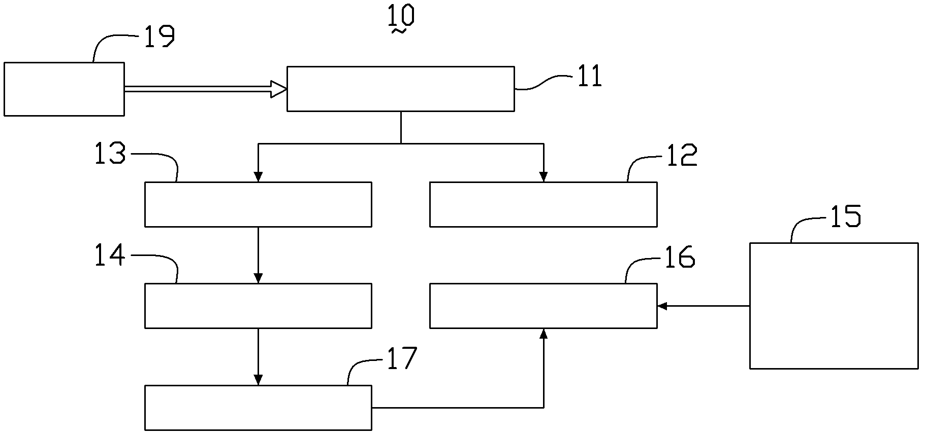
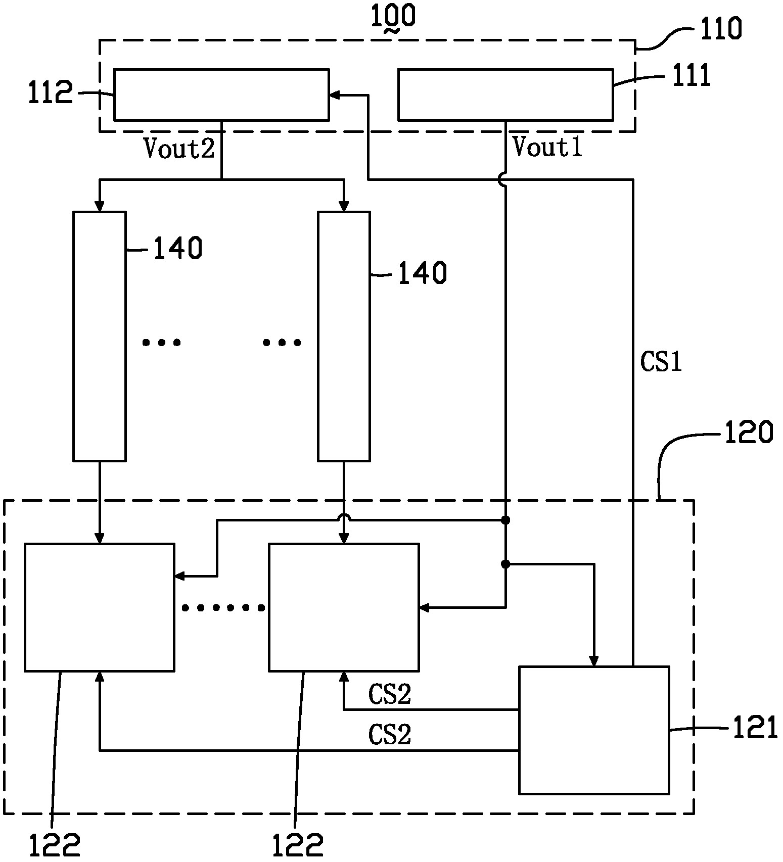
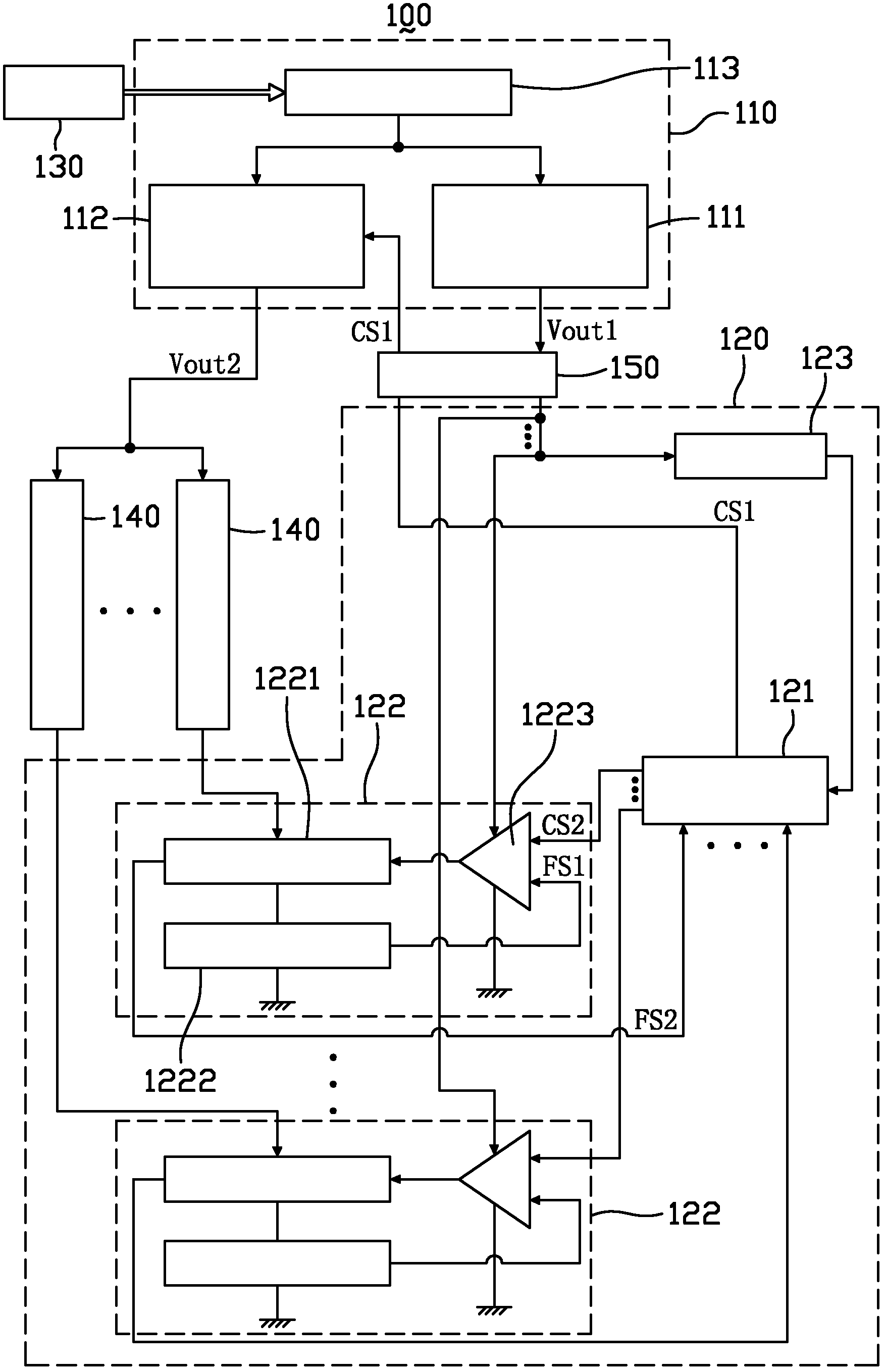
[0029] In order to further explain the technical means and effects of the present invention to achieve the intended purpose of the invention, the specific implementation methods, methods, steps, and structures of the LED backlight driving device proposed according to the present invention will be described below in conjunction with the accompanying drawings and preferred embodiments. , features and their effects are described in detail as follows.

[0030] The foregoing and other technical contents, features and effects of the present invention will be clearly presented in the following detailed description of preferred embodiments with reference to the drawings. Through the description of the specific implementation mode, the technical means and effects adopted by the present invention to achieve the predetermined purpose can be understood more deeply and specifically, but the attached drawings are only for reference and description, and are not used to explain the present inv...


PUM


Abstract

The invention provides an LED (Light Emitting Diode) backlight driving device used for driving multiple paths of LED light strings. The LED backlight driving device comprises a power supply circuit and a control circuit. The power supply circuit comprises a first power supply output module and a second power supply output module with adjustable voltage, wherein the first power supply output module is used for outputting a first power supply voltage; and the second power supply output module is used for outputting a second power supply voltage to an LED light string. The control circuit comprises a communication control module and multiple constant current control modules. The communication control module is supplied with power by the first power supply voltage and generates a control signal of the first type and multiple control signals of the second type. Each constant current control module is electrically connected with the communication control module and a corresponding LED light string respectively, wherein the communication control module controls the second power supply voltage output by the second power supply output module by using the first type of control signal and respectively controls the constant current control module by using the second type of control signals so that the currents in these LED light strings are controlled in a constant state and controlled to scan these LED light strings row by row.

Description

technical field [0001] The invention relates to the field of display technology, in particular to an LED backlight driving device for a liquid crystal display device. Background technique [0002] Flat panel display devices, such as liquid crystal display devices (liquid crystal display, LCD) have many advantages such as thinness, energy saving, and no radiation, so it has gradually replaced the traditional cathode ray tube (cathode ray tube, CRT) display device and has become the preferred mainstream. Currently, liquid crystal display devices have been widely used in various electronic devices such as digital televisions, computers, personal digital assistants, mobile phones, and digital cameras. [0003] Most of the existing liquid crystal display devices use light-emitting diodes (light-emitting diodes, LEDs) as backlight sources to provide light sources for the liquid crystal display devices. At present, LED backlights in liquid crystal display devices with 3D display ...

Claims


Application Information

Patent Timeline
Patent Type & Authority Patents(China)
IPC IPC(8): G09G3/34
Inventor 庞震华迟洪波徐爱臣辛晓光
Owner HISENSE VISUAL TECH CO LTD
Why Eureka
Try Eureka