Cover member and power supply device equipped with this cover member

A technology for cover parts and batteries, applied in battery pack parts, circuits, structural parts, etc., can solve problems such as reduced workability and locking

Active Publication Date: 2012-07-11
YAZAKI CORP
View PDF6 Cites 13 Cited by
  • Summary
  • Abstract
  • Description
  • Claims
  • Application Information

AI Technical Summary

Problems solved by technology

[0010] However, since the number of batteries in the current battery assembly increases with the increase in voltage, the cumulative tolerance (tolerance caused by the accumulation of tolerances for each battery) is larger than that of conventional products. Therefore, when stacked on the battery assembly When the connection box of the bus bar module is provided with an elastic part for absorbing tolerances, the length of the connection box changes due to the elastic part, etc., and the interval between the plurality of protrusions also changes accordingly. Therefore, if When the cover member disclosed in the above-mentioned Patent Document 1 is mounted on the connection box, the cover main body of the cover member and the locking claws of the pair of opening and closing parts are displaced with respect to the protrusions of the connection box, making it difficult to lock them. There is a problem that workability at the time of installation is lowered because the claws are locked with each protrusion.

Method used


Image

  • Cover member and power supply device equipped with this cover member
  • Cover member and power supply device equipped with this cover member
  • Cover member and power supply device equipped with this cover member

Examples


Embodiment Construction

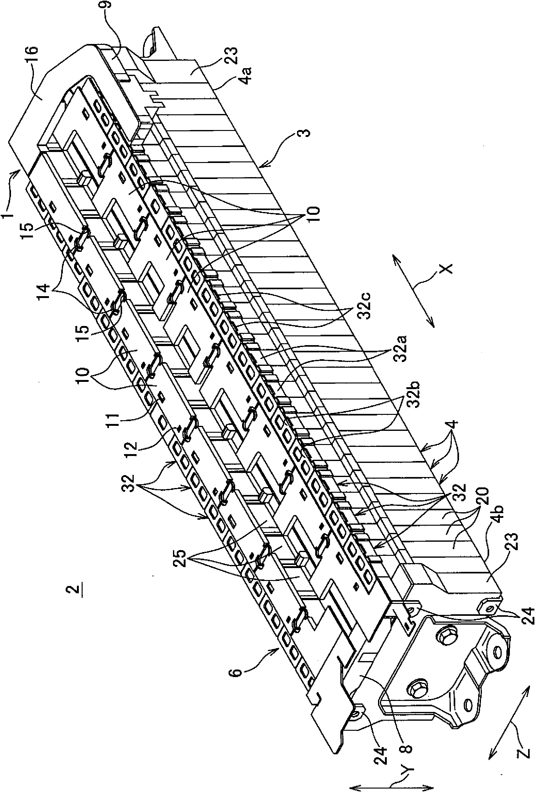
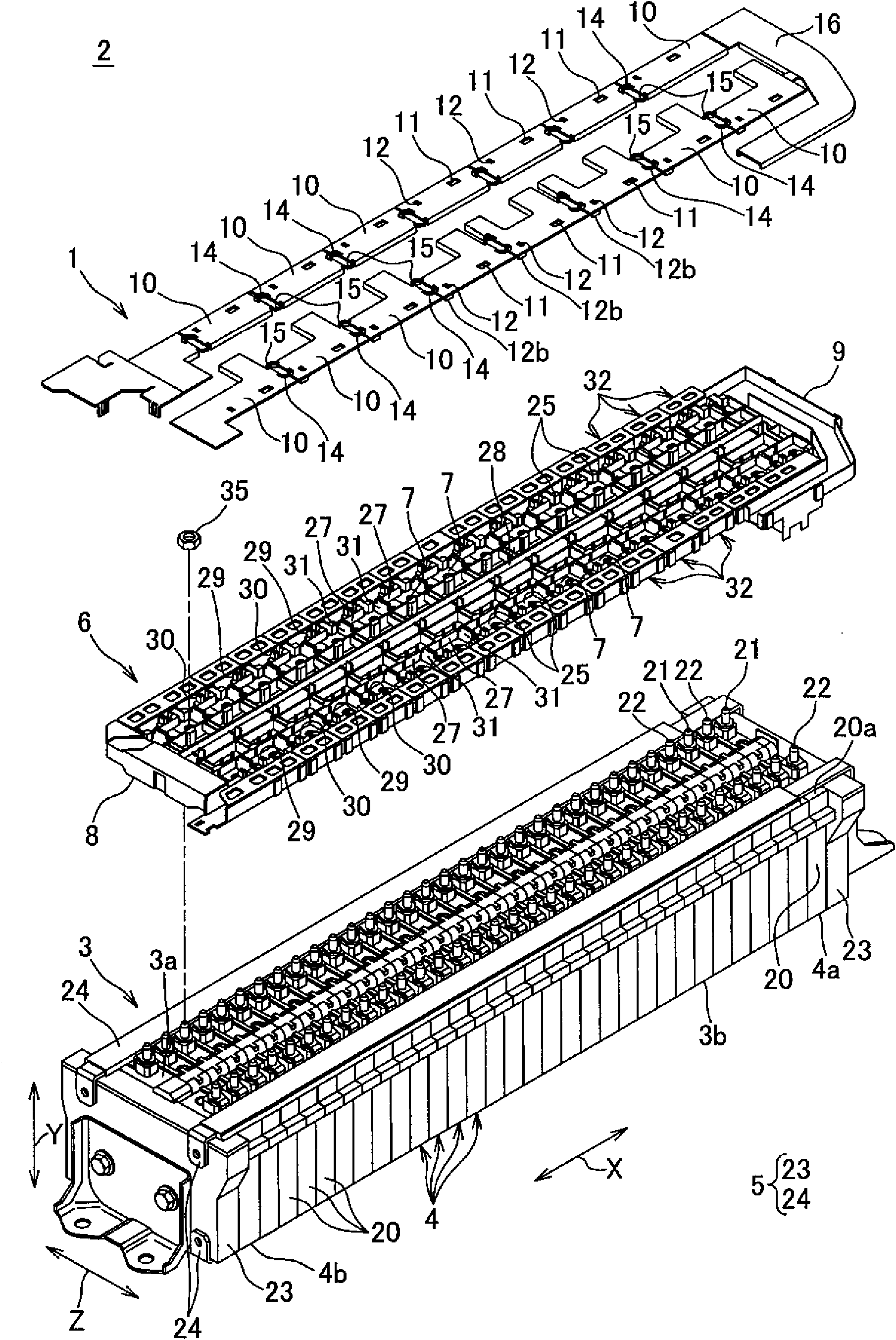
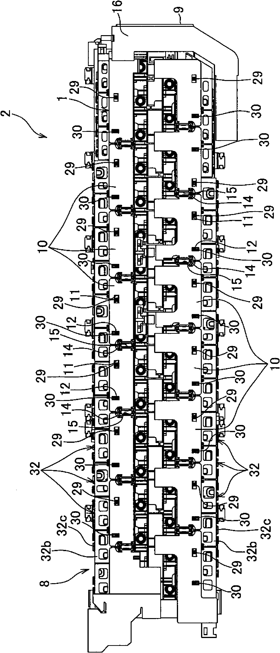
[0035] Below, refer to Figure 1 to Figure 7 , and a cover member and a power supply device including the cover member according to an embodiment of the present invention will be described. Configuration of cover member 1 according to one embodiment of the present invention figure 1 and so on as shown in the power supply unit 2. The power supply unit 2 is mounted on an electric vehicle running with driving force from an electric motor, a hybrid vehicle running with both the driving force of an engine and the electric motor, and supplies electric power to the electric motor.

[0036] Power supply unit 2 such as figure 1 As shown, a battery assembly 3, a pair of electric wires (not shown) for outputting the voltage of the battery assembly 3 to the outside, a bus bar module 6 mounted on the battery assembly 3, and a Cover part 1 on busbar module 6 . The battery assembly 3 includes a plurality of batteries 4 and a fixing member 5 that stacks and fixes the plurality of batterie...


PUM


Abstract

In a power supply device, there has been a problem that when a bus bar module to which batteries are connected varies in length, it becomes difficult to attach a cover member. The bus bar module (6) comprises: a plurality of bus bars for connecting adjacent batteries in a battery assembly body to each other, the battery assembly body being formed by stacking a plurality batteries; a main body portion (8) having the bus bars attached thereto and being stacked on the battery assembly body; a plurality of alignment projections (29) provided on the main body portion; and a plurality of locking portions (30). The cover member (1) is installed adjacent to the bus bar module along the stacked direction (X) of the batteries and comprises: a plurality of cover portions (10) for covering each of the bus bars; and an elastic deformation portion (14) for coupling the adjacent cover portions so as to be able to be mutually displaced. Each of the cover portions comprises: an alignment opening (11) into which each of the alignment projections is inserted; and a locking receiving portion (12) by which each of the locking portions is locked. The alignment opening is shaped so as to be able to be inserted even when the positions of the alignment projections move along the direction (X), thereby solving the above problem.

Description

technical field [0001] The present invention relates to a power supply device used in hybrid vehicles, electric vehicles, etc., and more particularly to a cover member mounted on a bus bar module for connecting a plurality of batteries in a row, and a power supply device including the cover member. Background technique [0002] A power supply device as a drive source of the electric motor is mounted on an electric vehicle running using an electric motor, a hybrid vehicle running using an engine and an electric motor, and the like. This power supply unit is composed of a battery assembly composed of a plurality of batteries provided with a positive electrode at one end and a negative electrode at the other end in a state where the positive electrode and the negative electrode are adjacent to each other. The battery assembly is composed of a bus bar module on a surface provided with positive and negative electrodes, and a cover member attached to the bus bar module. [0003] ...

Claims


Application Information

Patent Timeline
Patent Type & Authority Applications(China)
IPC IPC(8): H01M2/10H01M2/20H01M50/147H01M50/209H01M50/271H01M50/503H01M50/507H01M50/51H01M50/517H01M50/522
CPCY02E60/12H01M2/043H01M2/206H01M2/1083H01M2/1077Y02E60/10H01M50/147H01M50/517H01M50/271H01M50/507H01M50/503H01M50/209H01M50/51H01M50/522
Inventor 小笠原茂之佐藤胜则山下清贵
Owner YAZAKI CORP
Why Eureka
Try Eureka