Spark gap

A technology for spark gaps and gaps, which is applied in the direction of spark gaps, spark gap components, circuits dedicated to spark gaps, etc., can solve the problems of long delay, high ignition discharge voltage, etc., to save costs, improve stability and reliability , Conducive to the effect of reliable operation

Active Publication Date: 2013-08-28
CHINA ELECTRIC POWER RES INST +1
View PDF6 Cites 0 Cited by
  • Summary
  • Abstract
  • Description
  • Claims
  • Application Information

AI Technical Summary

Problems solved by technology

Through a lot of experimental research work, it is found that the use of trigger discharge type sealing gap in the trigger system can improve the trigger reliability of the gap system, but only when the ignition discharge is performed on the electrode on one side of the trigger discharge type sealing gap, it has a serious polarity effect , the ignition discharge voltage under one voltage polarity is very low, while the ignition discharge voltage under the other polarity is very high, and the delay is large

Method used


Image

  • Spark gap

Examples


Embodiment Construction

[0021] The present invention will be described in further detail below in conjunction with the accompanying drawings.

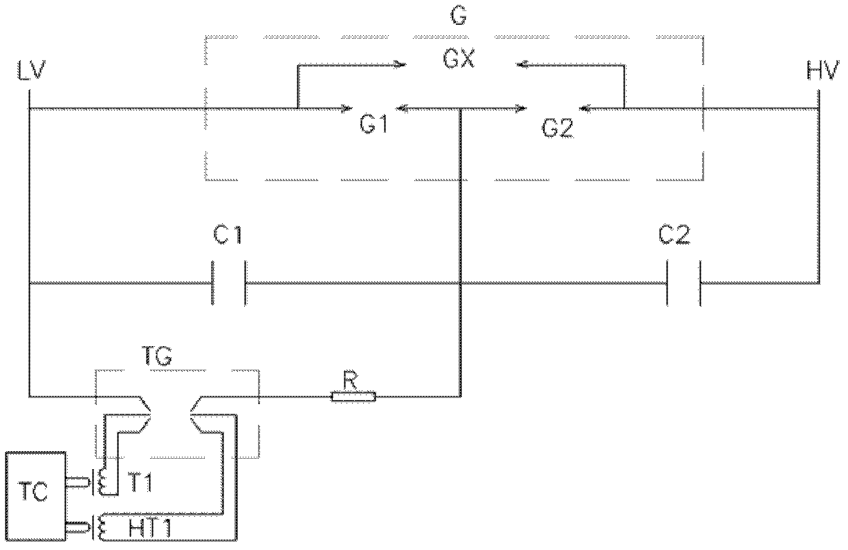
[0022] A spark gap with a single gap structure, the spark gap includes a self-discharging main gap G and a gap trigger system, the self-discharging main gap G includes a gap shell, flashover gaps G1, G2 and a freewheeling gap GX, the The flashover gaps G1 and G2 are connected in parallel with the freewheeling gap GX after being connected in series; the two ends of the spark gap are respectively connected with the high voltage end and the low voltage end; the gap trigger system is connected in parallel with the flashover gap G1 connected with the low voltage end.

[0023] The flashover gaps G1 and G2 are respectively equalized by voltage equalizing capacitors C1 and C2, the voltage equalizing capacitor C1 is connected in parallel with the flashover gap G1, and the voltage equalizing capacitor C2 is connected in parallel with the flashover gap G2.

[0024] The ...


PUM


Abstract

The invention provides a spark gap with a single-gap structure. The spark gap comprises a self-discharge type main gap G and a gap trigger system, wherein the self-discharge type main gap G comprises a gap housing, flashover gaps G1 and G2, and a follow-current gap GX, and the flashover gaps G1 and G2 are connected in series and then connected with the follow-current gap GX in parallel; both endsof the spark gap are connected with a high-voltage end and a low-voltage end respectively; and the gap trigger system and the flashover gap G1 which is connected to the low-voltage end are connected in parallel. The spark gap provided by the invention eliminates a polarity effect generated during ignition discharge performed on an electrode at one side of a trigger-discharge type sealing gap, so that reliable ignition discharge voltages with two polarities are very low, and the performance of protection coordination is effectively improved, thus improving the stability and reliability of trigger discharge when the spark gap is triggered under the same voltage. The spark gap is suitable for a series compensation device with a low rated voltage of a capacitor bank and for a series-resonancetype fault current limiter, as well as used for rapidly bypassing the capacitor bank.

Description

technical field [0001] The invention belongs to the technical field of electric equipment, and in particular relates to a spark gap with a single gap structure. Background technique [0002] The spark gap used in the series compensation device generally consists of two gaps connected in series to form a gap system. When the spark gap action is required to bypass the series compensation capacitor bank, the series compensation control and protection system sends a trigger command to the trigger control box through the optical fiber, and the trigger control box then sends The gap system sends a trigger signal that eventually discharges the spark gap, causing the spark gap to bypass the capacitor bank. Through a lot of experimental research work, it is found that the use of trigger discharge type sealing gap in the trigger system can improve the trigger reliability of the gap system, but only when the ignition discharge is carried out on the electrode on one side of the trigger ...

Claims


Application Information

Patent Timeline
Patent Type & Authority Patents(China)
IPC IPC(8): H01T1/20H01T2/02H01T14/00H01T15/00
Inventor 刘之方李国富董勤晓余辉李志远
Owner CHINA ELECTRIC POWER RES INST
Why Eureka
Try Eureka