Slowly-dropping escape device

A slow-descent escape device and escape device technology, applied in life-saving equipment, building rescue, etc., can solve the problems that the descending speed cannot be effectively controlled at the end of the descent, the performance of centrifugal friction damping is reduced, and the danger is high.

Inactive Publication Date: 2012-09-19
刘晓桐
View PDF11 Cites 8 Cited by
  • Summary
  • Abstract
  • Description
  • Claims
  • Application Information

AI Technical Summary

Problems solved by technology

Existing high-rise escape equipment has a complex structure and a large volume, and the damping device basically adopts a centrifugal friction damping device
During the descent of the lifeline, as the speed continues to increase, the friction between the centrifugal block and the friction ring of the centrifugal friction damping device continues to increase, but after the friction increases to a certain extent, due to the friction between the centrifugal block and the friction ring Friction generates heat, and the friction force will drop, resulting in a decline in the centrifugal friction damping performance at the end of the descent. The descent speed at the end of the descent cannot be effectively controlled, and the descent speed will become faster and faster, which is extremely dangerous.

Method used


Image

  • Slowly-dropping escape device
  • Slowly-dropping escape device
  • Slowly-dropping escape device

Examples


Embodiment 1

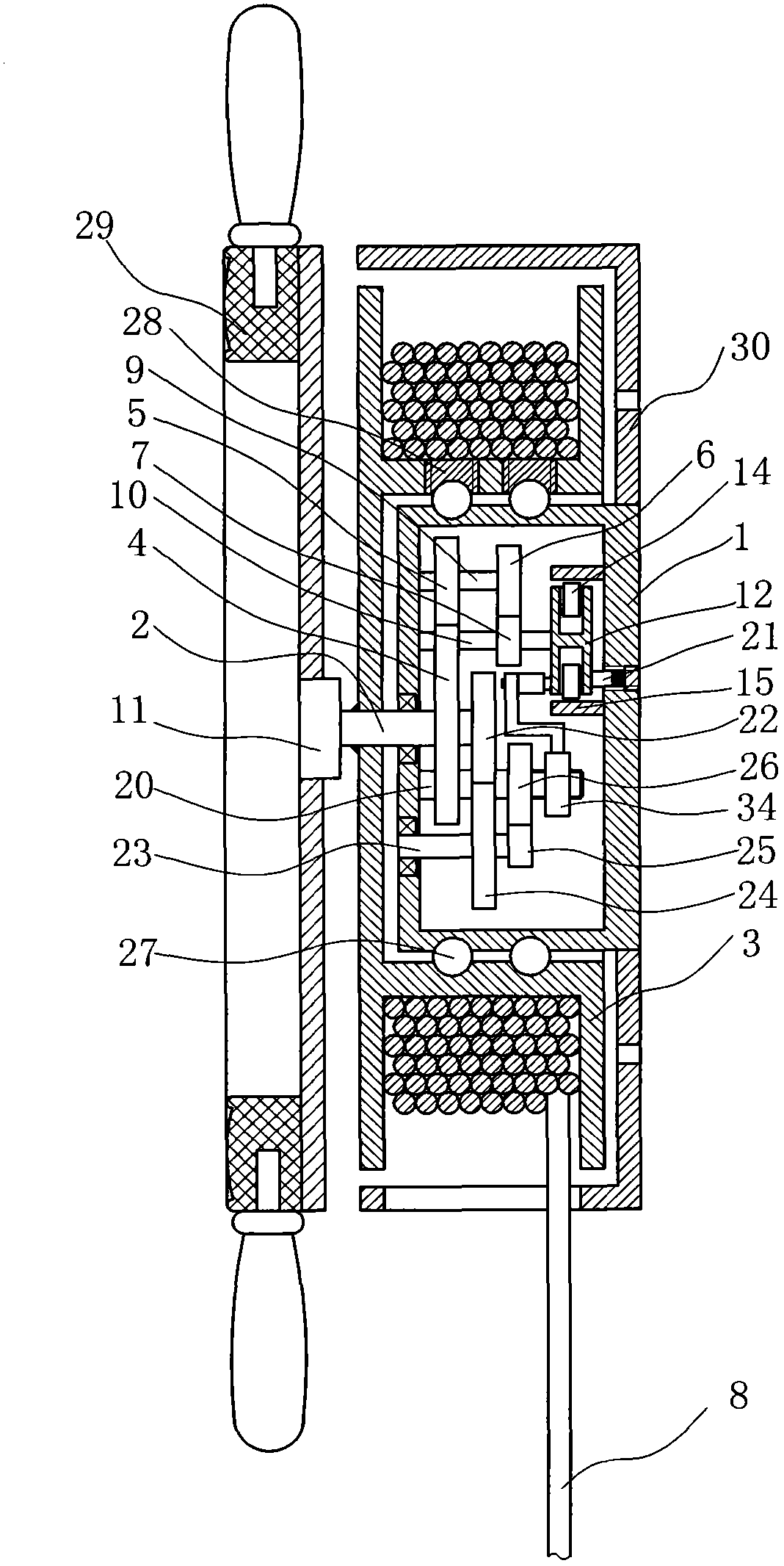
[0023] Such as figure 1 and figure 2 As shown, the slow descent escape device includes a base 30 on which a damping device housing 1 is installed, and the damping device housing 1 is a cylinder whose axis is perpendicular to the plane of the base 30. A central shaft 2 is installed in rotation on the damping device housing 1, and one end of the central shaft 2 protruding from the damping device housing 1 is fixedly installed with a cylindrical rope winding roller 3, and a lifesaving rope is wound on the rope winding roller 3 8. The rope winding roller 3 is rotatably set on the damping device housing 1, and the outer end of the rope winding roller 3 is equipped with a rope receiving device, and the damping device housing 1 and the rope winding roller 3 Ball grooves are arranged between the cover surfaces of the ball grooves, steel balls 27 are installed in the ball grooves, ball holes communicating with the ball grooves are arranged on the rope winding roller 3, and ball plugs...

Embodiment 2

[0030] Such as Figure 6 As shown, the structure of this embodiment is basically the same as that of Embodiment 1, the difference is that: the rope-receiving steering wheel 29 is directly fixed on the rope winding roller 3, and the rope-receiving steering wheel 29 and the rope winding One-way clutches are no longer provided between the rollers 3.


PUM


Abstract

The invention discloses a slowly-dropping escape device. The slowly-dropping escape device comprises a pedestal, wherein a damping device casing is installed on the pedestal; the damping device casing is a cylinder which is axially vertical to a pedestal plane; a central shaft is rotatably installed on the damping device casing; a cylindrical rope-winding roll is fixedly installed at one end of the central shaft extending out of the damping device casing; a life-saving rope is wound on the rope-winding roll; the rope-winding roll is rotatably sleeved on the damping device casing; a rope-reeling device is installed on the outer end part of the rope-winding roll; and the central shaft is in transmission connection with a centrifugal damping device and a progressive friction damping device inside the damping device casing. The centrifugal damping device and the progressive friction damping device ensure a slowly-dropping effect and avoid reduction of braking performance caused by reduction of centrifugal and frictional damping performance of a dropping tail section under the condition that the dropping height is relatively high; and after being installed, the volumes of the damping device casing and the rope-winding roll are relatively small, so that winding of the life-saving rope can be prevented and the life-saving rope is more reliable.

Description

technical field [0001] The invention relates to a high-rise building escape device. Background technique [0002] With the rapid development of urban construction, high-rise buildings continue to increase and people live densely. When sudden disasters occur, such as fires, earthquakes, etc., how to escape from high-rise buildings to safe areas as soon as possible is particularly important. Existing high-rise escape equipment has a complex structure and a large volume, and the damping device basically adopts a centrifugal friction damping device. During the descent of the lifeline, as the speed continues to increase, the friction between the centrifugal block and the friction ring of the centrifugal friction damping device continues to increase, but after the friction increases to a certain extent, due to the friction between the centrifugal block and the friction ring Friction generates heat, and the friction force will drop, resulting in a decline in the centrifugal fricti...

Claims


Application Information

Patent Timeline
Patent Type & Authority Applications(China)
IPC IPC(8): A62B1/08
Inventor 刘晓桐
Owner 刘晓桐
Why Eureka
Try Eureka